
Deep hole piston rod of side-thrust jack and machining method and application thereof

A processing method and a technology for a piston rod, applied in the direction of a hoisting device, etc., can solve the problems of increased raw material cost, increased manufacturing cost, increased manufacturing cost, etc., and achieve the effects of convenient disassembly and assembly, reduced raw material size, and convenient processing.

Pending Publication Date: 2020-07-28
SANY HEAVY EQUIP
View PDF0 Cites 0 Cited by
  • Summary
  • Abstract
  • Description
  • Claims
  • Application Information

AI Technical Summary

Problems solved by technology

Because the main structure of the side push jack mostly adopts the piston rod to drill a deep hole, that is, the internal liquid inlet structure, therefore, no matter whether the end of the piston rod is processed with a threaded liquid inlet hole or a welding joint mounting block, the diameter of the end of the piston rod is much larger than that of the piston rod. The diameter of the main body of the piston rod, which in turn causes the raw material selection and machining of the piston rod to increase the manufacturing cost virtually.
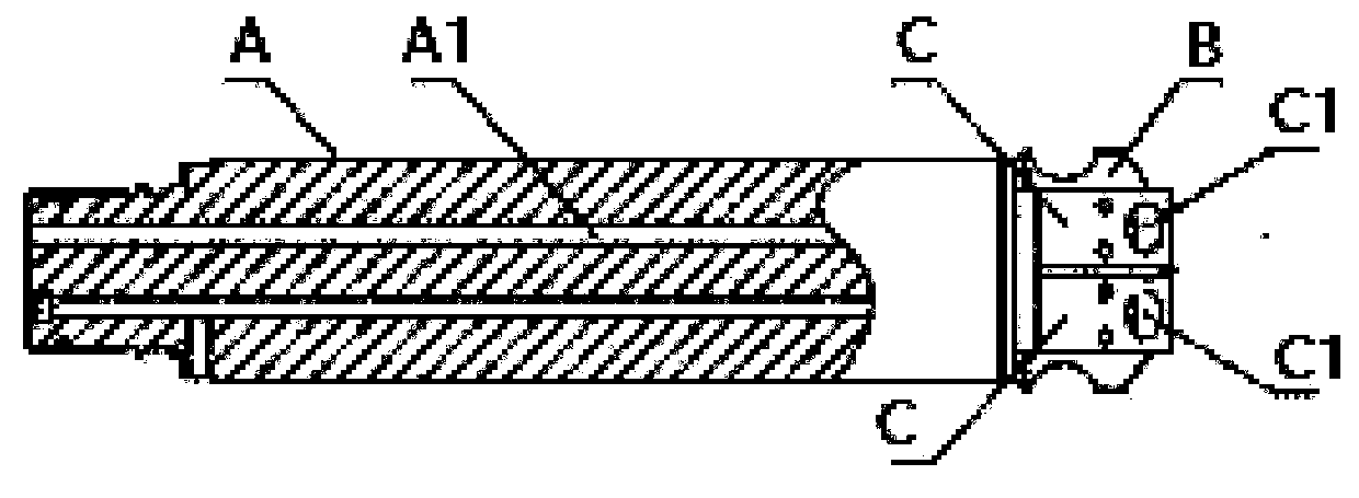
And the deep hole piston rod of the side push jack in the prior art adopts on the rod head of the piston rod to be welded on the mounting seat, which has the following disadvantages: (1) the mounting seat is welded at the rod head, so the diameter of the rod head is It needs to be increased to meet the size of the mount, and the cost of raw materials will increase
(4) If factors such as position degree and post-welding deformation are considered, the secondary processing of the sealing hole will increase the manufacturing cost and lengthen the manufacturing cycle

Method used


Image

  • Deep hole piston rod of side-thrust jack and machining method and application thereof
  • Deep hole piston rod of side-thrust jack and machining method and application thereof
  • Deep hole piston rod of side-thrust jack and machining method and application thereof

Examples


Embodiment Construction

[0039] In describing the present invention, it should be understood that the terms "center", "longitudinal", "transverse", "length", "width", "thickness", "upper", "lower", "front", " Orientation or position indicated by "back", "left", "right", "vertical", "horizontal", "top", "bottom", "inner", "outer", "clockwise", "counterclockwise", etc. The relationship is based on the orientation or positional relationship shown in the drawings, and is only for the convenience of describing the present invention and simplifying the description, rather than indicating or implying that the referred device or element must have a specific orientation, be constructed and operated in a specific orientation, therefore It should not be construed as a limitation of the present invention.

[0040] In addition, the terms "first" and "second" are used for descriptive purposes only, and cannot be interpreted as indicating or implying relative importance or implicitly specifying the quantity of indic...


PUM


Abstract

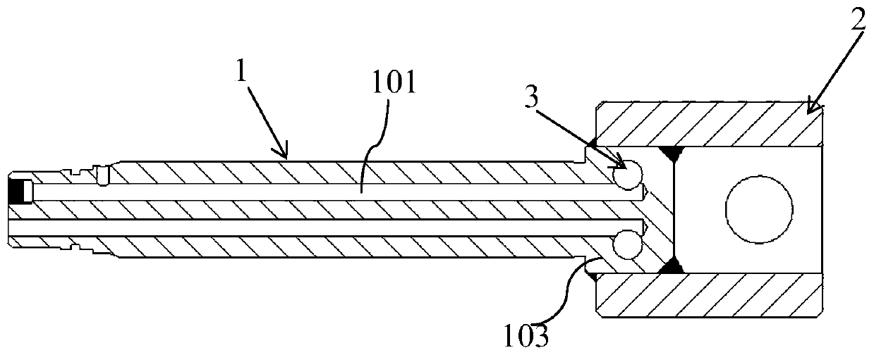
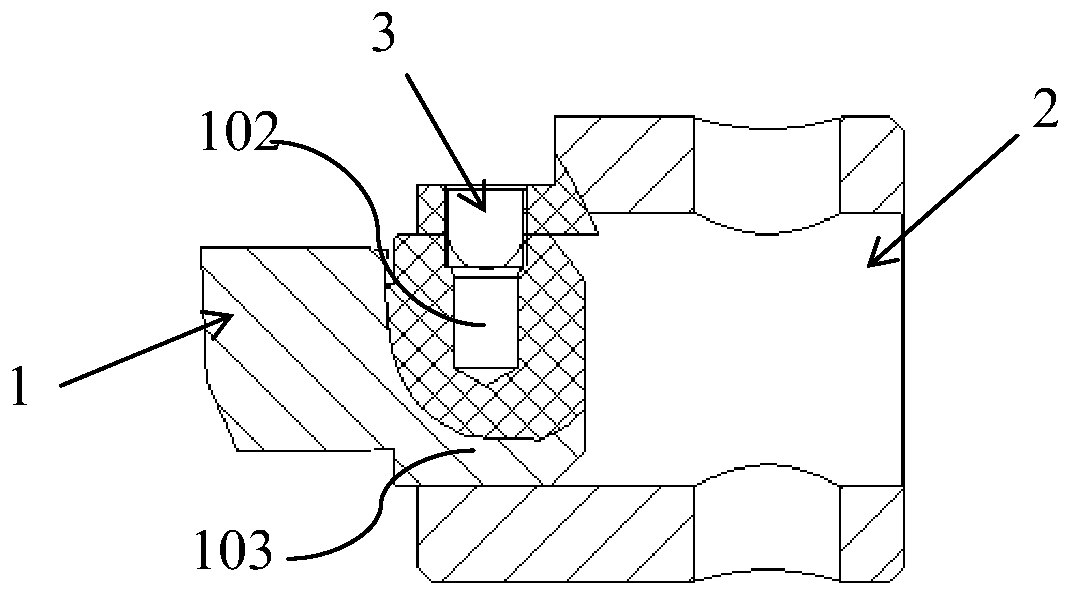
The invention discloses a deep hole piston rod of a side-thrust jack and a machining method and application thereof. The deep hole piston rod is changed from an overall structure into a rod body and fixing sleeve split structure, the size of raw materials for preparing the deep hole piston rod can be reduced, and then the machining cost is reduced; a deep hole is sequentially communicated with a sealing hole and a threaded hole, and the problem that in the prior art, a sealing face between a rod body and a fixing sleeve is frequently used, and the sealing face cannot be completely sealed in the mode of first-thread and second-sealing is solved; and the threaded hole penetrates through the side wall of the fixing sleeve, a rubber pipe connector can be conveniently connected, and the rubberpipe connector and a U-shaped clamp are more convenient to disassemble and assemble. In a word, the deep hole piston rod is changed from the overall structure into the rod body and fixing sleeve splitstructure, compared with a piston rod with a welding installation base structure, machining is more convenient, and the matching size precision is higher.

Description

technical field [0001] The invention belongs to the field of fully mechanized mining equipment in coal mines, and more specifically relates to a deep-hole piston rod of a side pusher jack and a processing method and application thereof. Background technique [0002] The side push jack with hydraulic support for coal mine is installed in the side push sleeve, wherein, one side of the side push jack is fixed with a lock pin, and the other side is movable in the side push sleeve. When the side push jack is working, it drives the side guard to extend and retract along the axial direction. Because the main structure of the side push jack mostly adopts the piston rod to drill a deep hole, that is, the internal liquid inlet structure, therefore, no matter whether the end of the piston rod is processed with a threaded liquid inlet hole or a welding joint mounting block, the diameter of the end of the piston rod is much larger than that of the piston rod. The diameter of the main bo...

Claims


Application Information

Patent Timeline
IPC IPC(8): B66F3/24B66F3/25B23P15/00
CPCB66F3/24B66F3/25B23P15/00B66F2700/05
Inventor 李健姜仁坤韩相冬
Owner SANY HEAVY EQUIP
Learn More