Supercharge Your Innovation With Domain-Expert AI Agents!

Vibration pile machine for immersed tube sand-gravel pile and pile forming method

A technology for sand and gravel piles and pile drivers, which is applied in sheet pile walls, buildings, infrastructure projects, etc., can solve the problems of reduced diameter pile quality, poor diameter reduction and pile quality, broken piles, etc., so as to reduce broken piles. The probability of occurrence, the effect of improving the quality of piles and improving the construction progress

Inactive Publication Date: 2020-07-28
SINOHYDRO BUREAU 1 CO LTD
View PDF8 Cites 0 Cited by
  • Summary
  • Abstract
  • Description
  • Claims
  • Application Information

AI Technical Summary

Problems solved by technology

[0003] Due to the earth dam formation of Qian'an Huaaopao project is fluid plastic clay and silt, its fluidity and the lateral pressure from the surrounding silt make it difficult to unload sand and gravel materials during the construction process of immersed tube sandstone piles, and it is difficult to meet the design requirements. Pile quality; and in the construction process, the problems of broken piles, shrinkage and poor quality of piles are prone to occur, which will cause serious troubles to the quality of consolidation and drainage of soft soil foundations and construction progress
[0004] To sum up, the existing problems in the prior art are: (1) When the existing vibratory pile driver drives piles on fluid plastic clay and silt, due to its fluidity and lateral pressure from the surrounding silt, the immersed pipe During the construction of sand and gravel piles, it is difficult to cut sand and gravel materials, and it is difficult to achieve the pile quality required by the design
[0005] (2) The existing vibratory pile driver is prone to broken piles, diameter shrinkage and poor quality of piles during the construction process, causing serious troubles to the quality of consolidation and drainage of soft soil foundations and construction progress

Method used


Image

  • Vibration pile machine for immersed tube sand-gravel pile and pile forming method
  • Vibration pile machine for immersed tube sand-gravel pile and pile forming method
  • Vibration pile machine for immersed tube sand-gravel pile and pile forming method

Examples


Embodiment Construction

[0048] In order to further understand the content, features, and effects of the present invention, the following embodiments are exemplified and described in detail below with the accompanying drawings.

[0049] In view of the problems existing in the prior art, the present invention provides a vibrating pile machine and a method for forming a pile for sunk pipe gravel piles. The present invention will be described in detail below with reference to the accompanying drawings.

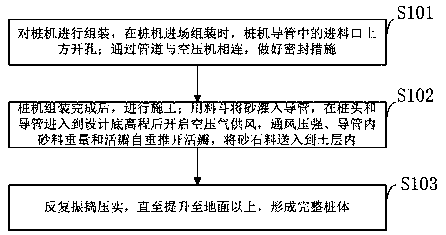
[0050] Such as figure 1 As shown, the method for forming a pile by a vibrating pile machine for a sunken sand-gravel pile provided by an embodiment of the present invention includes the following:

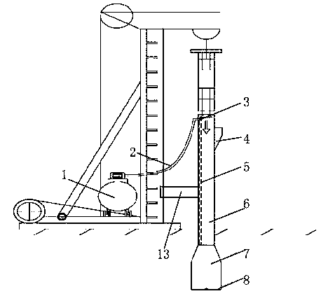
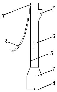
[0051] S101: Assemble the pile driver. When the pile driver is assembled, make a hole above the feed port in the pipe of the pile driver; connect it to the air compressor through a pipe, and take sealing measures.

[0052] S102: After the pile driver is assembled, carry out construction; pour sand into the pipe with a...


PUM


Abstract

The invention belongs to the technical field of building instruments, and discloses a vibration pile machine for an immersed tube sand-gravel pile and a pile forming method. The method comprises the steps that the pile machine is assembled, and when the pile machine enters a field to be assembled, a hole is formed in the upper portion of a feeding opening in a guide pipe of the pile machine; the guide pipe is connected with an air compressor through a pipeline, and sealing measures are taken; after the pile machine is assembled, construction is conducted; a hopper is used for pouring sand andgravel into the guide pipe, after a pile head and the guide pipe enter the designed bottom elevation, the air compressor is started to supply air, and the ventilation pressure intensity, the weight ofthe sand and gravel in the guide pipe and the self weight of a valve push away the valve, so that the sand and gravel are conveyed into a soil layer; and the sand and gravel are repeatedly vibrated and compacted until the sand and gravel achieve above the ground to form a complete pile body. According to the machine and the method, the compressed air is input into the guide pipe through the air compressor while the sand and gravel are input into the guide pipe, so that the pressure in the guide pipe is larger than the lateral pressure generated by flow plastic layer sludge on the sand and gravel; the sand and gravel enter a sludge layer to form the pile body, so that the design requirement of the immersed tube sand-gravel pile is met; and meanwhile, the sand-gravel pile forming quality isimproved, and the probability of pile breakage is reduced.

Description

Technical field [0001] The invention belongs to the technical field of construction equipment, and in particular relates to a vibrating pile machine and a pile forming method for sunk pipe sand-stone piles. Background technique [0002] At present, the closest existing technology: the vibratory pile driver uses its high-frequency vibration to vibrate the pile body with high acceleration, and transmits the vertical vibration generated by the machine to the pile body, causing the soil structure around the pile to change due to vibration and its strength reduce. The soil around the pile body is liquefied to reduce the frictional resistance between the pile side and the soil body, and then the pile is sunk into the soil by the downward pressure of the pile machine, the vibrating sinker and the pile body's own weight. When pulling out the pile, pull up the pipe with the lifting force of the pile machine while one side is vibrating. The excitation force required by the piling machine...

Claims


Application Information

Patent Timeline
IPC IPC(8): E02D7/18
CPCE02D7/18
Inventor 滕昊赵贝贝冯佳楠王恩沛何欣乔海
Owner SINOHYDRO BUREAU 1 CO LTD
Features
  • R&D
  • Intellectual Property
  • Life Sciences
  • Materials
  • Tech Scout
  • Unparalleled Data Quality
  • Higher Quality Content
  • 60% Fewer Hallucinations
Learn More