
Vibration isolation equipment and railway vehicle adopting equipment

A kind of equipment and vibration isolation technology, applied in the field of rail vehicles, can solve the problems of physical hazards, poor vibration isolation effect of passive vibration isolators, strong penetrating power, etc., to increase the service life of equipment, good vibration isolation effect, and improve the riding environment Effect

Active Publication Date: 2020-07-28
CRRC QINGDAO SIFANG CO LTD
View PDF5 Cites 0 Cited by
  • Summary
  • Abstract
  • Description
  • Claims
  • Application Information

AI Technical Summary

Problems solved by technology

However, the low-frequency vibration and noise generated by rail transit vehicles during driving greatly affect the comfort of passengers. Low-frequency mechanical waves and noise have strong penetrating power during transmission and are difficult to attenuate, causing harm to the body. These low-frequency noise and vibration mainly come from Vehicle equipment excites vibration, and the equipment installation space is extremely limited, within 50mm
[0003] Traditional vibration isolators are divided into active vibration isolators and passive vibration isolators. Active vibration isolators have the disadvantages of high cost, large size, high working environment requirements, and active energy consumption; Poor and the vibration isolation frequency does not meet the design requirements, and the use of traditional vibration isolators to achieve low-frequency vibration isolation requires low natural frequency of the vibration isolator, which means that the structural stiffness of the vibration isolator is low, and it is necessary to balance the vibration isolation effect and system stability of the system sex

Method used


Image

  • Vibration isolation equipment and railway vehicle adopting equipment
  • Vibration isolation equipment and railway vehicle adopting equipment
  • Vibration isolation equipment and railway vehicle adopting equipment

Examples


Embodiment Construction

[0038] Below in conjunction with accompanying drawing and specific embodiment the present invention is described in further detail:

[0039] In order to make the object, technical solution and advantages of the present invention clearer, the present invention will be further described in detail below in conjunction with the accompanying drawings and embodiments. It should be understood that the specific embodiments described here are only used to explain the present invention, not to limit the present invention.

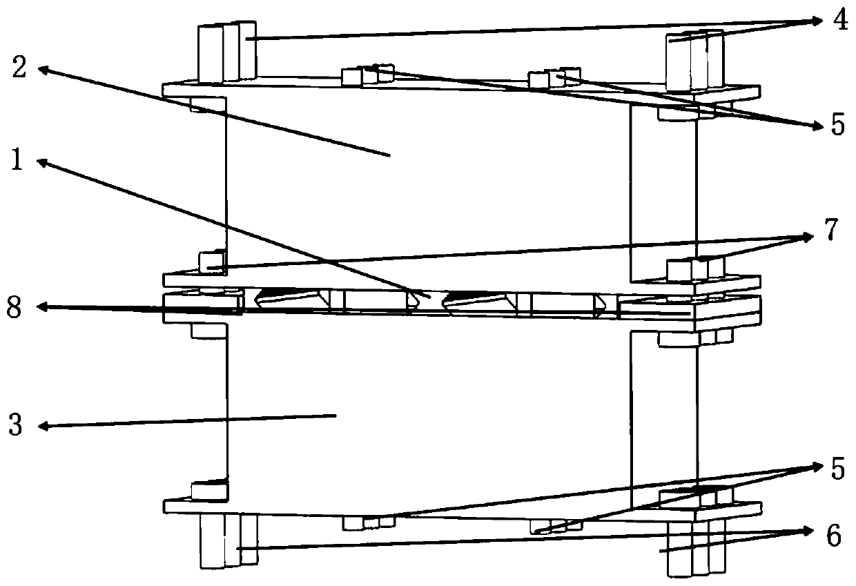
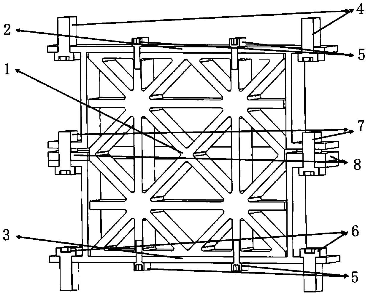
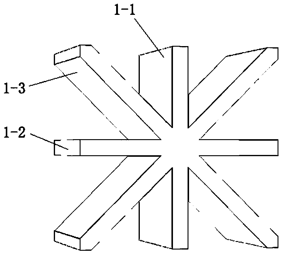
[0040] Such as figure 1 with figure 2 As shown, a vibration isolation device includes one or more vibration-damping components 1 arranged between the vehicle-mounted equipment and the vehicle body. The vibration-damping components 1 are provided with an upper outer frame 2 and a lower outer frame 3 . In the present invention, the damping component 1 is set to have negative stiffness characteristics, forming a forbidden band that elastic waves cannot pass through i...


PUM


Abstract

The invention relates to vibration isolation equipment and a railway vehicle adopting the equipment. The vibration isolation equipment comprises one or more vibration reduction components arranged between vehicle-mounted equipment and a vehicle body. Each vibration reduction component comprises a supporting and bearing portion and an energy dissipation portion, wherein the supporting and bearing portion is used for supporting the vehicle-mounted equipment and the vehicle body and bearing the vibration isolation equipment, and the energy dissipation portion is used for carrying out energy dissipation through responding resonance to bending waves and vertical elastic waves and internal friction heating. The stability of the vibration isolation equipment is achieved through the supporting andbearing portions, the energy dissipation portions are adopted for carrying out energy dissipation on elastic wave responding resonance and internal friction heating formed within the low frequency range, and the vibration isolation effect is achieved.

Description

technical field [0001] The invention relates to a vibration isolation and noise reduction device for low frequency bands, in particular to a vibration isolation device and a rail vehicle using the device. Background technique [0002] Rail transit has the advantages of punctuality, large passenger capacity, green energy saving, and convenience. It has increasingly become the first choice for people to commute and travel in the middle and long distances. However, the low-frequency vibration and noise generated by rail transit vehicles during driving greatly affect the comfort of passengers. Low-frequency mechanical waves and noise have strong penetrating power during transmission and are difficult to attenuate, causing harm to the body. These low-frequency noise and vibration mainly come from Vehicle equipment excites vibration, and the equipment installation space is extremely limited, within 50mm. [0003] Traditional vibration isolators are divided into active vibration i...

Claims


Application Information

Patent Timeline
Patent Type & Authority Applications(China)
IPC IPC(8): F16F1/26F16F1/30
CPCF16F1/26F16F1/30
Inventor 徐刚李盈利高宝杰王京军赵艳菊
Owner CRRC QINGDAO SIFANG CO LTD
Learn More