A garbage pyrolysis gasifier

A technology of pyrolysis gasification and pyrolysis furnace, which is applied in the direction of incinerators, lighting and heating equipment, combustion types, etc., can solve the problems of low thermal conductivity, hinder the decomposition of plastic center parts, and low plastic decomposition efficiency, so as to improve contact area, the effect of increasing the contact surface

Active Publication Date: 2022-04-26
中开水生态治理有限公司
View PDF14 Cites 0 Cited by
  • Summary
  • Abstract
  • Description
  • Claims
  • Application Information

AI Technical Summary

Problems solved by technology

[0002] Plastic waste is treated by pyrolysis, which breaks the macromolecules in plastic waste, and a high-quality low-sulfur fuel oil obtained through pyrolysis improves the recycling of plastic waste. However, due to the low thermal conductivity of plastic waste During the pyrolysis process of the plastic inside the gasifier, the outside of the plastic is heated to the temperature of the melting point, while the temperature of the center of the plastic is lower, and the outer plastic is carbonized first, which hinders the decomposition of the center of the plastic, resulting in Inefficient decomposition of plastic in the center of the plastic

Method used


Image

  • A garbage pyrolysis gasifier
  • A garbage pyrolysis gasifier
  • A garbage pyrolysis gasifier

Examples


Embodiment 1

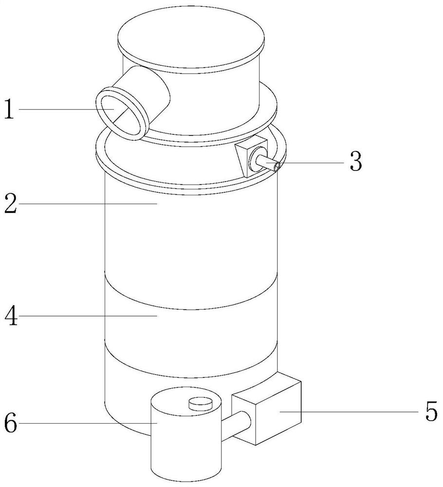
[0024] as attached figure 1 To attach Image 6 Shown:

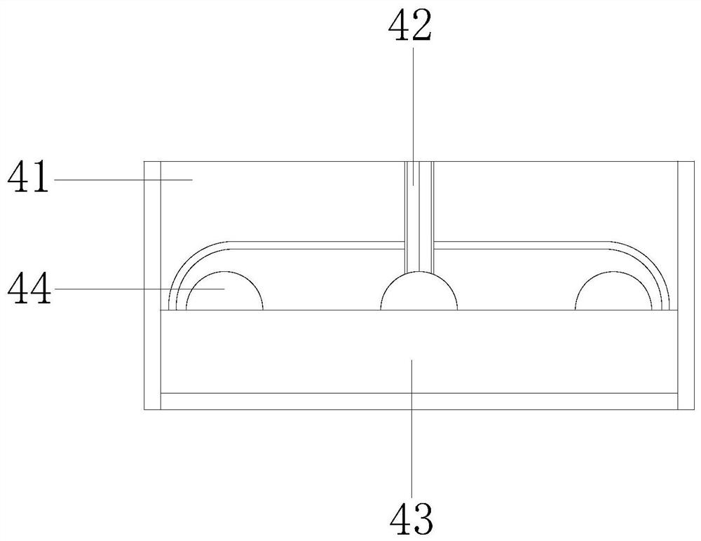
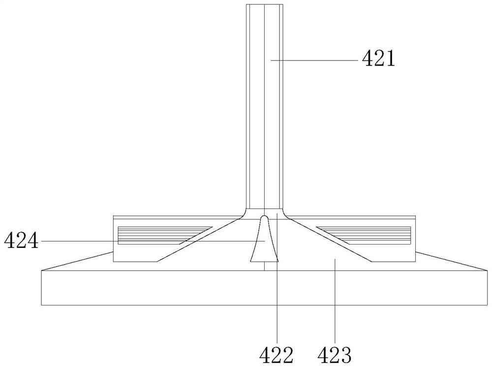
[0025] A garbage pyrolysis gasification furnace of the present invention, its structure includes an inlet 1, a pyrolysis furnace 2, an air outlet pipe 3, a turning mechanism 4, a steam inlet 5, and a burner 6, and the inlet 1 is installed on the upper end of the pyrolysis furnace 2 And communicate with each other, the upper end of the pyrolysis furnace 2 is embedded with an outlet pipe 3, the bottom of the pyrolysis furnace 2 is equipped with a turning mechanism 4, the steam inlet 5 is fixedly installed on the outside of the bottom of the turning mechanism 4, and the steam inlet 5 communicates with the burner 6, the turning mechanism 4 includes a housing 41, a rotating mechanism 42, an underflow mechanism 43, and a middle heat conduction mechanism 44, and the upper end of the housing 41 is fixedly installed on the lower end of the pyrolysis furnace 2 and communicates with each other. A rotating mechanism 42 is installed...

Embodiment 2

[0033] as attached Figure 7 To attach Figure 8 Shown:

[0034] Wherein, the middle heat conduction mechanism 44 includes a conduction pipe 441, a transfer pipe 442, and a heat conduction ball 443. Inside the bottom flow mechanism 43, a transfer pipe 442 is provided at the upper end of the conduction pipe 441 and communicates with each other. The transfer pipe 442 adopts The gap fit is installed inside the lower end of the heat conduction ball 443. The conduction pipe 441 has a circular structure, and is better installed at the junction of the inclined flow plate 423 and the bottom flow groove 431. The transmission pipe 442 and the heat conduction ball 443 are equipped with four One, to better pyrolyze the middle end of the melted plastic waste, and the transfer pipe 442 has a narrow upper part and a wider lower part, so as to improve the transfer efficiency of the steam generated by the steam inlet 5.

[0035] Wherein, the heat conduction ball 443 includes a limiting plate...


PUM


Abstract

The invention discloses a garbage pyrolysis gasification furnace, the structure of which comprises an inlet, a pyrolysis furnace, a gas outlet pipe, a turning mechanism, a steam inlet, and a burner. Embedded with an air outlet pipe, the plastic waste inside the turning mechanism is pyrolyzed, and the plastic waste in the middle is moved upward through the structure of the plate body, and at the same time, the melted plastic waste in the middle is flowed downward through the inlet and flow ports, and the upward flow is carried out. The middle and lower flow circulates, and at the same time, through the sliding of the sliding plate, the flow tube inside the supporting plate makes the molten garbage in the middle flow down, avoiding the carbonization of the external plastic garbage in the first step, and the steam is transmitted through the transmission tube, to the center The molten plastic waste inside is pyrolyzed, and at the same time, after the expansion body is heated and expanded, the connecting rod protrudes from the inside of the hollow ball, increasing the contact surface with the melted plastic waste, thereby ensuring that the plastic in the center is decomposed.

Description

technical field [0001] The invention relates to the field of garbage pyrolysis and gasification, and more specifically relates to a garbage pyrolysis gasification furnace. Background technique [0002] Plastic waste is treated by pyrolysis, which breaks the macromolecules in plastic waste, and a high-quality low-sulfur fuel oil obtained through pyrolysis improves the recycling of plastic waste. However, due to the low thermal conductivity of plastic waste During the pyrolysis process of the plastic inside the gasifier, the outside of the plastic is heated to the temperature of the melting point, while the temperature of the center of the plastic is lower, and the outer plastic is carbonized first, which hinders the decomposition of the center of the plastic, resulting in The plastic in the center of the plastic breaks down inefficiently. Contents of the invention [0003] The technical solution adopted by the present invention to achieve the technical purpose is: the pyro...

Claims


Application Information

Patent Timeline
Patent Type & Authority Patents(China)
IPC IPC(8): G06F1/20F23G5/027F23G5/44
CPCF23G5/0273F23G5/444F23G5/44
Inventor 张仁清
Owner 中开水生态治理有限公司
Why Eureka
Try Eureka