Depth controlled photoablation of human or animal tissue

Active Publication Date: 2015-11-19
ADVANCED OSTEOTOMY TOOLS - AOT
View PDF4 Cites 12 Cited by
  • Summary
  • Abstract
  • Description
  • Claims
  • Application Information

AI Technical Summary

Benefits of technology

[0023]Preferably, the adjusting structure comprises a current adjuster for adjusting current or voltage or both, current and voltage simultaneously, provided to the laser source propagating the laser beam and/or a pulse adjuster for adjusting a length of a pulse of the laser beam. With such an adjusting structure, the photoablation device can be capable of efficiently and precisely adjusting intensity of the laser beam.
[0024]Preferably, the photoablation device further comprises an acoustic sensor being arranged to sense an acoustic wave generated by the laser beam hitting the tissue and to provide a correspondin

Problems solved by technology

A common problem in known laser induced photoablation of human or animal hard tissue relates to controlling cutting depth and beam intensity.
Such collateral damages can occur, e.g. as carbonization, due to heating caused by inappropriate laser beam intensities in tissue neighboring the osteotomic or cutting line.
Making these problems even more difficult to handle, in contrast to the mentioned non-biological materials, human or animal hard tissues of th

Method used


Image

  • Depth controlled photoablation of human or animal tissue
  • Depth controlled photoablation of human or animal tissue
  • Depth controlled photoablation of human or animal tissue

Examples


Embodiment Construction

[0033]In the following description certain terms are used for reasons of convenience and are not to be interpreted as limiting. The terms “right”, “left”, “up” and “down” refer to directions in the figures. The terminology comprises the explicitly mentioned terms as well as their derivations and terms with a similar meaning.

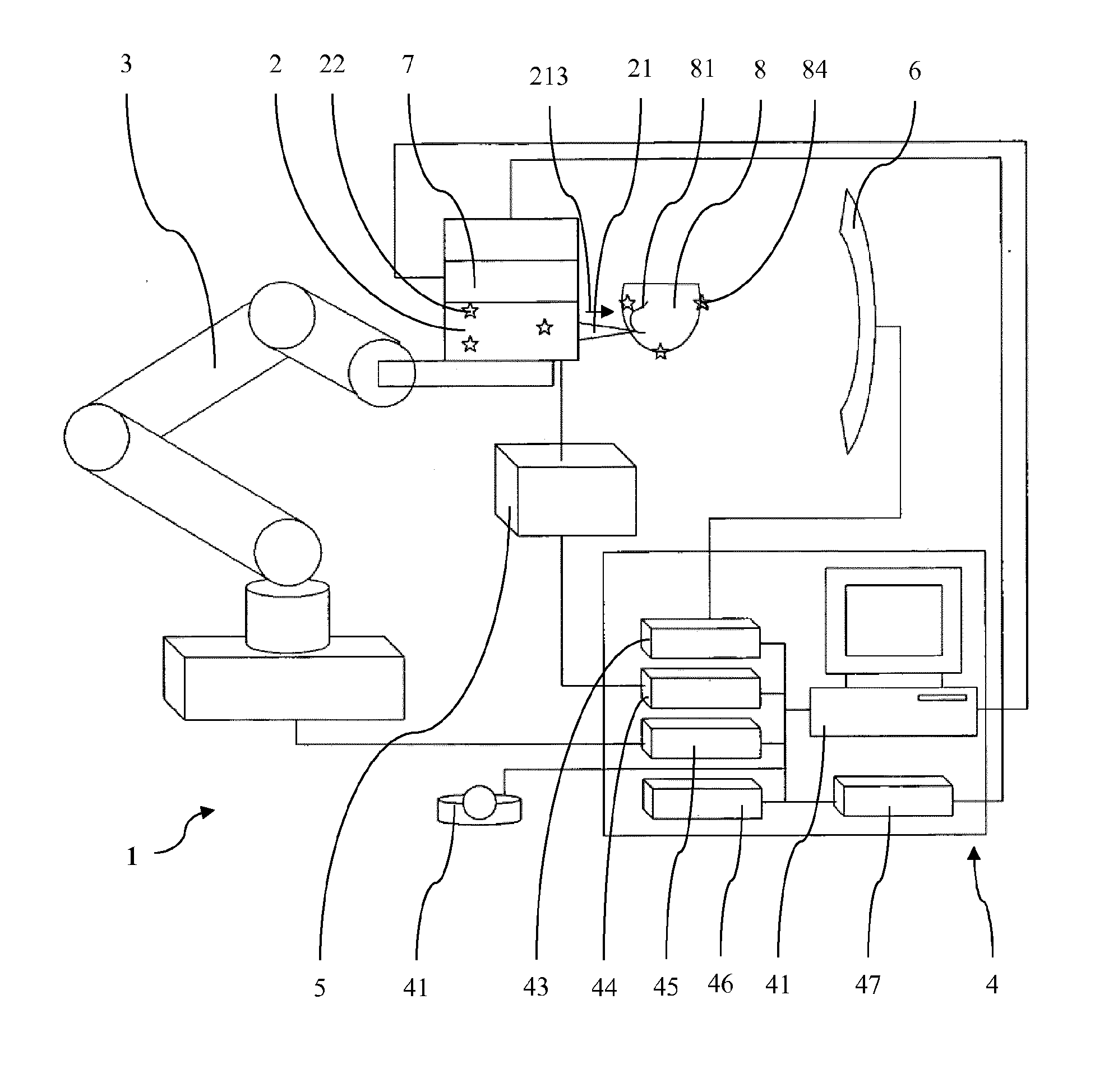
[0034]FIG. 1 shows an embodiment of a photoablation device 1 according to the invention for depth controlled photoablation of a target bone tissue 8. The photoablation device 1 comprises a robot arm 3 as positioning device, an evacuation supply system 5, an auto-tracker 6 as position detector, a laser source 2, a microphone 7 as acoustic sensor and a controller unit 4 having a computer 41.

[0035]The laser source 2 is fixedly mounted to a platform provided at a free end of the robot arm 3. It is arranged to propagate a focused laser beam 21 into a direction of propagation 213 which, in FIG. 1, is from left to right. The laser source 2 is connected to a current adju...


PUM


Abstract

A photoablation device (1) for photoablation of human or animal tissue (8) comprises: a laser source (2) being arranged to propagate a focused laser beam (21) with a beam waist, wherein a radius of the laser beam (21) increases from the beam in waist into a direction of propagation (213) of the laser beam (21); an adjusting structure (41, 47) being arranged for adjusting an intensity of the laser beam (21); a position detector (6) for detecting a position of the laser source (2) in relation to the tissue (8); a positioning device (3) being arranged to move the laser source (2) in relation to the tissue (8); and a controller unit (4). The controller unit is arranged to define a photoablation zone of the laser beam (21), wherein the photoablation zone ends in a cutting face which is located at the beam waist or offset from the beam waist into the direction of propagation (213) of the laser beam (21), to adjust an intensity at the cutting face of the photoablation zone of the laser beam (21) by means of the adjusting structure (41, 47), and to move the laser beam (21) towards the tissue (8) by means of the positioning device (3), wherein the position of the laser source (2) detected by the position detector (6) is evaluated. The device according to the invention allows for conveniently controlling and determining the depth of the photoablation into the tissue by the movement of the laser beam towards the tissue. In particular, the depth can correspond to the movement of the laser beam towards the tissue. Furthermore, the photoablation energy or intensity can precisely be adjusted in accordance with the tissue. Like this, it is possible to take account of the individual properties of the tissue and to minimize heating of the tissue such that, e.g., carbonization of the tissue can be prevented.

Description

TECHNICAL FIELD[0001]The present invention relates to a method in which a focused laser beam with a beam waist is provided to a human or animal tissue and more particularly to a device with which such a method can be implemented and a computer program controlling such a device. Such methods, devices and computer programs can be used for photoablating and thereby cutting human or animal tissue.BACKGROUND ART[0002]For cutting human or animal hard tissue such as bone or nail tissue various methods and devices are applied today. Thereby, in recent years photoablation by means of laser beams turned out to be a feasible alternative to known tools and methods. Particularly, in osteotomy laser induced photoablation became of increasing interest as an alternative to known mechanical tools such as saws, chisels or drills. The aim of such laser induced photoablation is to increase preciseness and operability while decreasing collateral damages, e.g. caused by direct contact of the mechanical t...

Claims


Application Information

Patent Timeline
IPC IPC(8): A61B18/20A61B5/00
CPCA61B18/20A61B5/0066A61B2018/00577A61B2018/00648A61B2018/0088A61B2018/00845A61B2017/0019A61B2018/0072A61B2017/00747A61B2018/00565A61B2018/00642A61B18/203A61B2018/00601A61B2090/049A61B2090/3735A61B2034/2063A61B34/30
Inventor BRUNO, ALFREDO E.CATTIN, PHILIPPEDEIBEL, WALDEMAR
Owner ADVANCED OSTEOTOMY TOOLS - AOT
Why Eureka
Try Eureka