Clean indoor pollution source pollution gas rapid removal system

A technology to remove systems and pollution sources, applied in air-conditioning systems, heating methods, lighting and heating equipment, etc., can solve the problems of increasing FFU energy consumption, increasing the number of air returns of air-conditioning systems, and inability to quickly remove polluted air, so as to avoid pollution. Effect

Inactive Publication Date: 2021-08-27
BEIJING UNION UNIVERSITY
View PDF10 Cites 0 Cited by
  • Summary
  • Abstract
  • Description
  • Claims
  • Application Information

AI Technical Summary

Problems solved by technology

When there is a new pollution source, the traditional removal method is to increase the return air frequency of the air conditioning system, or increase the output of dozens of FFU (fan filter unit with self-powered power), and for local pollution caused by mobile pollution sources, use the same If the treatment method is not used, it will not only not be able to quickly remove the polluted gas, but will also increase the energy consumption of the FFU

Method used


Image

  • Clean indoor pollution source pollution gas rapid removal system
  • Clean indoor pollution source pollution gas rapid removal system
  • Clean indoor pollution source pollution gas rapid removal system

Examples


Embodiment Construction

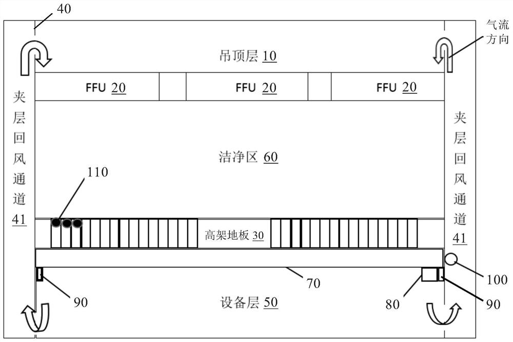
[0015] like figure 1 As shown, the rapid removal system of pollution source pollution gas in the clean room of the present invention is used for the removal of pollution gas discharged from fixed or mobile pollution sources in the clean room. The clean room includes a load-bearing wall 40 and an elevated floor 30. The load-bearing wall 40 is provided with a mezzanine return air passage 41. The equipment floor 50 is located below the elevated floor 30. The clean area 60 is above the elevated floor 30. The suspended ceiling is above the clean area 60. Layer 10, a plurality of FFU (fan filter unit with self-powered) 20 are installed below the suspended ceiling layer 10 . In the present invention, the composition of the clean room is an existing technology in this field, so it will not be described in detail, and the raised floor 30 and FFU 20 are existing decorative components or equipment in this field.

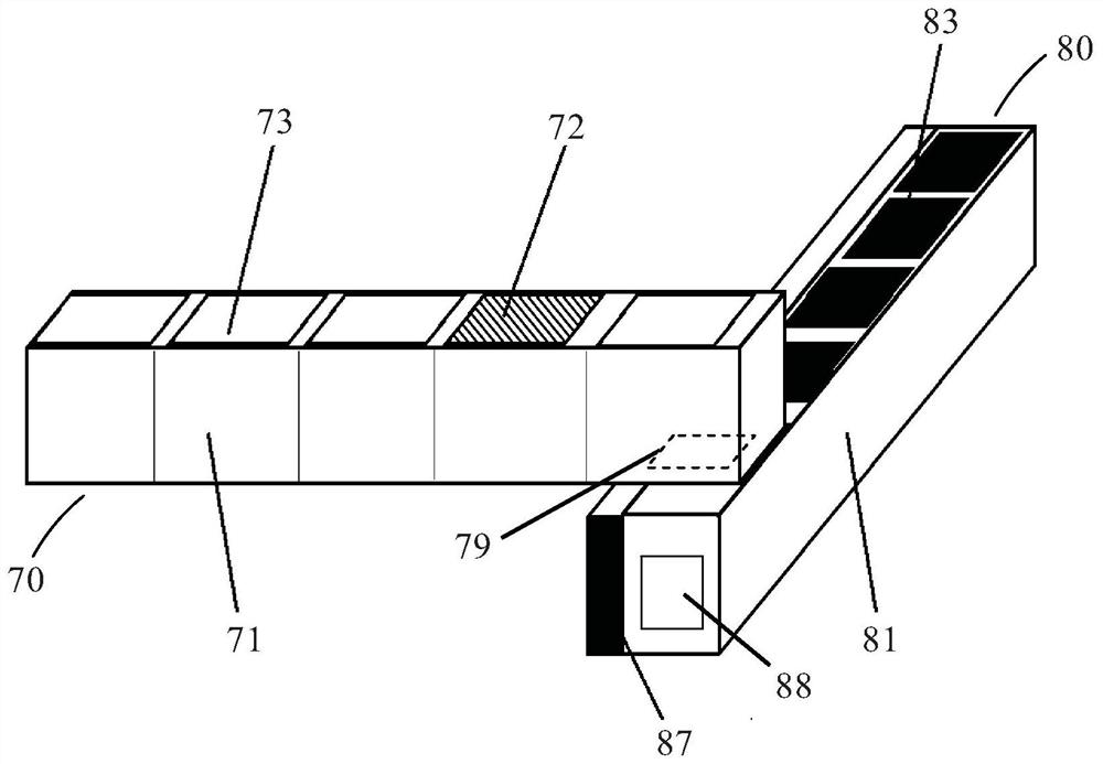
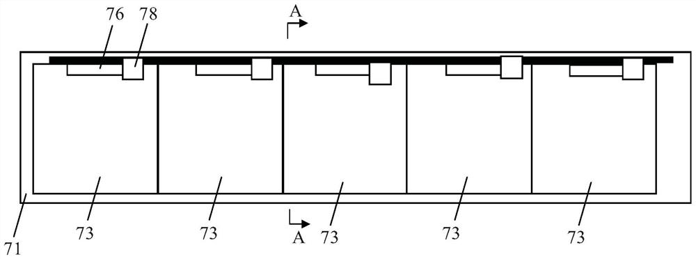
[0016] like Figure 1 to Figure 7 As shown, the system for quickly remov...


PUM


Abstract

The invention discloses a system for quickly removing polluted gas from pollution sources in a clean room. A plurality of photoelectric sensor groups are installed in the gaps of the hole plate of the raised floor. In the equipment layer, there are suction pipes, connection pipes, guide rails and guide rail drive devices. The suction pipes are connected to the guide rail drive devices and can be installed on two parallel guide rails in a translational manner. The connection pipe is fixedly installed in the equipment layer, the connection pipe is located below the suction pipe and vertically intersects with the suction pipe, and one end of the connection pipe is connected to the compressor motor. The raised floor, the suction pipe, the connection pipe, the compressor motor and the interlayer return air passage are connected together to form a passage for discharging the polluted gas generated by the pollution source in the clean area. The photoelectric sensor group, the suction pipe, the guide rail driving device and the compression motor are connected with the controller. The invention can quickly remove the pollution sources in the clean room, especially the polluted air produced by the mobile pollution sources.

Description

technical field [0001] The invention relates to a system for quickly removing pollution sources in clean rooms such as electronic clean workshops, especially the pollution gas produced by mobile pollution sources, and belongs to the technical field of pollution cleaning equipment. Background technique [0002] The pollution sources in clean rooms such as electronic clean workshops are mainly people, various processed materials and processing equipment. When there is a new pollution source, the traditional removal method is to increase the return air frequency of the air conditioning system, or increase the output of dozens of FFU (fan filter unit with self-powered power), and for local pollution caused by mobile pollution sources, use the same If the treatment method is not used, it will not only not be able to quickly remove the polluted gas, but will also increase the energy consumption of the FFU. Therefore, the research on how to accurately and quickly remove pollution ...

Claims


Application Information

Patent Timeline
IPC IPC(8): F24F3/167F24F11/89F24F13/02F24F13/32F04D29/70
CPCF04D29/703F24F13/0227F24F13/32F24F11/89F24F8/10
Inventor 杨志成方羽琛王丰周倪辉
Owner BEIJING UNION UNIVERSITY
Why Eureka
Try Eureka