Supercharge Your Innovation With Domain-Expert AI Agents!

Fault detection method and device

A fault detection and post-fault technology, applied to fault locations, measuring devices, circuit devices, etc., can solve problems such as voltage fluctuations in the measurement system and fault information cannot be accurately determined, and achieve the effect of improving accuracy

Inactive Publication Date: 2020-07-28
ANNING BUREAU OF ULTRA HIGH VOLTAGE TRANSMISSION
View PDF6 Cites 4 Cited by
  • Summary
  • Abstract
  • Description
  • Claims
  • Application Information

AI Technical Summary

Problems solved by technology

[0003] In the related technology, the DC voltage divider is formed by connecting the high-voltage arm and the low-voltage arm in series, and the secondary voltage divider is connected in parallel with the low-voltage arm. The voltage fluctuation of the system makes it difficult to accurately determine the specific fault information

Method used


Image

  • Fault detection method and device
  • Fault detection method and device
  • Fault detection method and device

Examples


Embodiment Construction

[0032] Reference will now be made in detail to exemplary embodiments, examples of which are illustrated in the accompanying drawings. When the following description refers to the accompanying drawings, the same numerals in different drawings refer to the same or similar elements unless otherwise indicated. The implementations described in the following exemplary examples do not represent all implementations consistent with the present invention. Rather, they are merely examples of apparatuses and methods consistent with aspects of the invention as recited in the appended claims.

[0033] Furthermore, the drawings are merely schematic illustrations of the present disclosure and are not necessarily drawn to scale. Some of the block diagrams shown in the drawings are functional entities and do not necessarily correspond to physically or logically separate entities.

[0034] In recent years, in order to meet the situation of uneven energy distribution between the east and the we...


PUM


Abstract

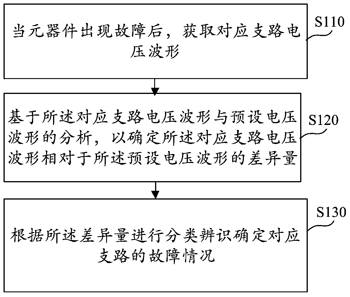
The invention provides a fault detection method and device. The method comprises the steps of: when a component has a fault, obtaining a voltage waveform of a corresponding branch; based on analysis of the corresponding branch voltage waveform and a preset voltage waveform, determining the difference amount of the corresponding branch voltage waveform relative to the preset voltage waveform; and performing classification identification according to the difference quantity to determine the fault condition of the corresponding branch, wherein the difference quantity of the preset voltage waveform is determined through analysis of the corresponding branch voltage waveform and the preset voltage waveform; the difference quantity of the voltage waveform can clearly identify and determine the fault condition of the corresponding branch under classification and identification, so that the fault condition of the corresponding branch can be determined on the total multiple branches, and the accuracy of fault detection is further improved.

Description

technical field [0001] The invention relates to a detection model in intelligent decision-making, in particular to a fault detection method and device. Background technique [0002] With the development and construction of high-voltage direct current transmission system, the position of the converter station, which bears more and more transmission capacity, is becoming more and more important in the power system. Among them, the direct current converter station uses a direct current voltage divider to measure the direct current voltage. [0003] In the related technology, the DC voltage divider is formed by connecting the high-voltage arm and the low-voltage arm in series, and the secondary voltage divider is connected in parallel with the low-voltage arm. The voltage fluctuation of the system makes it difficult to accurately determine the specific fault information. Contents of the invention [0004] The present disclosure aims to provide a fault detection method and dev...

Claims


Application Information

Patent Timeline
Patent Type & Authority Applications(China)
IPC IPC(8): G01R31/08
CPCG01R31/085G01R31/088H02H3/50
Inventor 黄剑湘陈诺韩建伟李少森杨涛徐峰陈图腾王丹彭福琨朱旭东李浩孙豪袁虎强颜波邓本飞杨光鞠翔朱盛强任君丁丙侯刘超梁钰华胡瑞赵世伟王加磊张丹霖
Owner ANNING BUREAU OF ULTRA HIGH VOLTAGE TRANSMISSION
Features
  • R&D
  • Intellectual Property
  • Life Sciences
  • Materials
  • Tech Scout
  • Unparalleled Data Quality
  • Higher Quality Content
  • 60% Fewer Hallucinations
Learn More