
Method and system for suppressing DC continuous commutation failure based on rapid forced excitation of phase modifier

A commutation failure, DC system technology, applied in the field of suppressing DC continuous commutation failure, can solve the problems of insufficient use of the reactive power support capacity of the camera, long delay time, etc. The ability to fail, the effect of improving the accuracy of risk prediction

Active Publication Date: 2020-07-28
ELECTRIC POWER RES INST OF STATE GRID ZHEJIANG ELECTRIC POWER COMAPNY
View PDF7 Cites 5 Cited by
  • Summary
  • Abstract
  • Description
  • Claims
  • Application Information

AI Technical Summary

Problems solved by technology

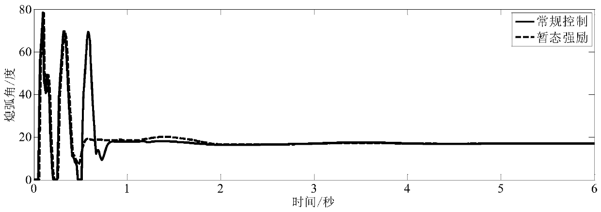
[0009] Conventional camera control methods have certain shortcomings in suppressing DC continuous commutation failures, which are mainly reflected in: the start signal comes from the converter station’s prediction logic for continuous commutation failures, and the delay time is long; The excitation control logic remains unchanged, affected by the fluctuation of the AC bus voltage due to commutation failure, the reactive power support capability of the condenser itself is not fully utilized

Method used


Image

  • Method and system for suppressing DC continuous commutation failure based on rapid forced excitation of phase modifier
  • Method and system for suppressing DC continuous commutation failure based on rapid forced excitation of phase modifier
  • Method and system for suppressing DC continuous commutation failure based on rapid forced excitation of phase modifier

Examples


Embodiment 1

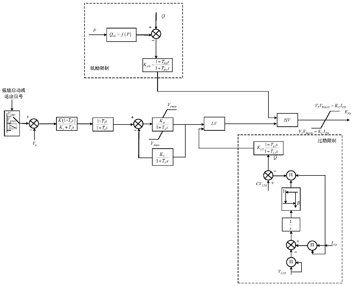
[0045] like figure 1 As shown, a method of suppressing DC continuous commutation based on the fast and forced excitation of the condenser, the steps are as follows:

[0046] A. Calculate the DC commutation failure critical voltage U according to the DC system structural parameters and current operating status cr1 and U cr2 ;

[0047] B. Monitoring the AC bus voltage U of the DC converter station L , if the AC line of the power grid connected to the DC receiving end converter station fails, the AC bus voltage U of the converter station L below U cr2 , start the transient strong excitation control of the condenser;

[0048] C. After the condenser starts the transient strong excitation control, the voltage reference value of the excitation controller terminal V ERR0 switch to V ERR1 , the V ERR1 It is the middle terminal voltage reference value of the phase controller excitation control terminal voltage control loop during the transient forced excitation;

[0049] D. In ...

Embodiment 2

[0079] like Image 6 As shown, a suppressed DC continuous commutation system based on the fast and forced excitation of the condenser is characterized in that it includes:

[0080] Commutation failure critical voltage calculation module: calculate DC commutation failure critical voltage U according to DC system structural parameters and current operating status cr1 and U cr2 ;

[0081] Transient strong excitation control start-up module of the condenser: monitor the AC bus voltage U of the DC converter station L , if the AC line of the power grid connected to the DC receiving end converter station fails, the AC bus voltage U of the converter station L below U cr2 , start the transient strong excitation control of the condenser;

[0082] Transient excitation control terminal voltage reference switching logic module: After the condenser starts the transient strong excitation control, the voltage reference value of the excitation controller terminal V ERR0 switch to V ERR1...


PUM


Abstract

The invention discloses a method and system for suppressing DC continuous commutation failure based on transient forced excitation of a phase modifier. According to the technical scheme adopted by theinvention, the method comprises the steps of calculating a critical commutation bus voltage of DC commutation failure according to structural parameters and a current operation state of a DC system,and taking the critical commutation bus voltage as a starting threshold value and an exit threshold value of transient forced excitation control of the phase modifier; when a near-zone AC line of a DCconverter station breaks down, enabling the phase modifier to start transient forced excitation control and continuously work in a top value overexcitation state; in the DC commutation failure process, detecting the bus voltage, the active power, the reactive power and the extinction angle of the converter station in real time, and judging whether the risk of the next commutation failure occurs in the commutation failure recovery process of the direct current or not. The method can improve the prediction accuracy of the continuous commutation failure risk of the DC system, and shortens the transient forced excitation starting time of the phase modifier; and the transient reactive power supporting capability of the phase modifier is fully utilized, and the capability of inhibiting continuous commutation failure of the converter station of the phase modifier is improved.

Description

technical field [0001] The invention relates to the field of safety and stability analysis of power systems, in particular to a method and system for suppressing DC continuous commutation failure based on fast and forced excitation of capacitors. Background technique [0002] my country's energy distribution and load distribution show a trend of east-west differentiation. The northwest region has large-scale thermal power and photovoltaic and other new energy sources, and the southwest region has a large amount of hydropower resources, while the load centers are mostly concentrated in the central and eastern coastal areas. Therefore, long-distance and large-scale transmission of power resources has become the trend of my country's future power system. [0003] Compared with the AC transmission method, the DC transmission method has many obvious advantages. DC transmission lines are low in cost, long in life, large in transmission capacity, low in loss, and do not need to in...

Claims


Application Information

Patent Timeline
IPC IPC(8): H02J3/36H02J3/16
CPCH02J3/16H02J3/36Y02E40/30Y02E60/60
Inventor 王龙飞华文楼伯良王博文周升彧申屠磊旋董炜赵一琰
Owner ELECTRIC POWER RES INST OF STATE GRID ZHEJIANG ELECTRIC POWER COMAPNY
Learn More