Drawing frame and compaction device for spinning machine

A drafting device and compressing device technology, which is applied to spinning machines, drafting equipment, textiles and papermaking, etc., can solve the problem of not being able to ensure that the hollow part is pressed against the roller, and achieve the effect of reliable and uniform compression

Active Publication Date: 2020-07-28
MASCHINENFABRIK RIETER AG
View PDF9 Cites 0 Cited by
  • Summary
  • Abstract
  • Description
  • Claims
  • Application Information

AI Technical Summary

Problems solved by technology

The disadvantage of this type of device is that a press-fit element alone doe

Method used


Image

  • Drawing frame and compaction device for spinning machine
  • Drawing frame and compaction device for spinning machine
  • Drawing frame and compaction device for spinning machine

Examples


Embodiment Construction

[0034] In the following description of the alternative embodiments, the same reference numerals are used for identical and / or at least similar features of technical solution and / or operating principle. If these features are not described in detail again, their technical solutions and / or working principles are equivalent to those of the previously described features.

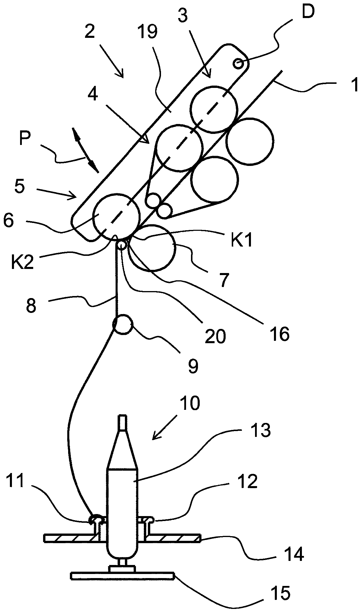
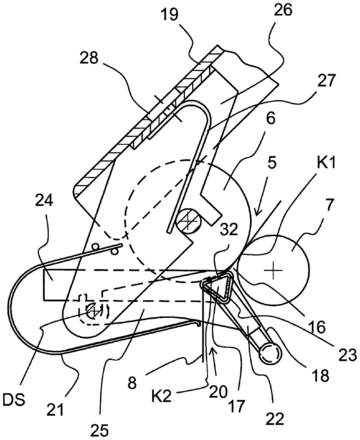
[0035] figure 1 is a schematic illustration of a longitudinal section of a spinning machine, in particular a ring spinning machine with a compression device 20 . Several components of the spinning machine, namely the drafting device 2 and the spinning device 10 are schematically shown in the figure. The drafting device 2 is composed of three roller pairs: an input roller pair 3 , a belt roller pair 4 and an output roller pair 5 . The output roller pair 5 is formed by the output top roller 6 and the output bottom roller 7 . The two rollers of a roller pair come together and form a clamping point at their point ...


PUM


Abstract

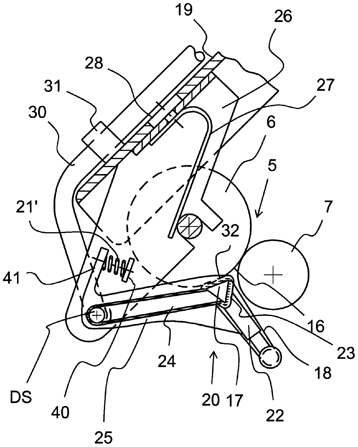
The invention relates to a drawing frame for a spinning machine, comprising top and bottom rollers, a loading arm (19) on which the top rollers of the drawing frame (2) are mounted, an output roller pair (5) which is formed by an output top roller (6) and an output bottom roller (7), and, mounted on the loading arm (19), a loading unit (26) on which the output top roller (6) is mounted. A pneumatic compaction device for compacting a drawn fiber composite (8) is arranged downstream of the output roller pair (5) of the drawing frame (2), said compaction device having a suction tube (17) which can be subjected to suction. The suction tube (17) is mounted on a lever (25), the lever (25) is rotatably and/or displaceably mounted on the loading unit (26), and a spring device (21; 21', 40, 41) isprovided which acts on the suction tube (17) and/or the lever (25) in order to elastically press the suction tube (17) against the output top roller (6) or the output bottom roller (7). A corresponding compaction device comprises a suction tube (17) which can be subjected to suction and a loading unit (26), wherein the suction tube (17) is mounted on a lever (25), the lever (25) is rotatably and/or displaceably mounted on the loading unit (26), and a spring device (21; 21', 40, 41) is provided which acts on the suction tube (17) and/or the lever (25) in order to be able to elastically press the suction tube (17) against the output top roller (6) or the output bottom roller (7).

Description

technical field [0001] The invention relates to a drafting device for a spinning machine with a top roller and a bottom roller, with a load arm on which the top roller of the drafting device is arranged, with a delivery top roller and a delivery bottom roller A pair of output rollers is formed, with a load assembly arranged on the load arm, an output top roller is arranged on the load assembly, and a pair of output rollers downstream of the drafting device is provided for the drafted fiber A pneumatic compression device for mass compression, the compression device having a suction pipe that can be sucked, and a corresponding compression device. Background technique [0002] A drafting device for a spinning machine comprises at least two roller pairs, between which the fiber assembly (Faserverband) is drafted based on the different rotational speeds of the roller pairs. In the case where the drafted fiber aggregate leaves the drafting device after a pair of rollers and is se...

Claims


Application Information

Patent Timeline
IPC IPC(8): D01H5/72
CPCD01H5/72
Inventor G·斯塔莱克G·沙夫勒K·胡贝尔
Owner MASCHINENFABRIK RIETER AG
Why Eureka
Try Eureka