Powder feeding control and recovery device

A recovery device and powder feeding device technology, which is applied in the field of additive manufacturing, can solve the problems of increased processing costs and powder waste, and achieve the effects of low manufacturing cost, prevention of powder waste, and simple structure

Inactive Publication Date: 2020-07-31
成都青石激光科技有限公司
View PDF9 Cites 3 Cited by
  • Summary
  • Abstract
  • Description
  • Claims
  • Application Information

AI Technical Summary

Problems solved by technology

[0004] The object of the present invention is to provide a powder feeding control and recovery device, which solves the above-mentioned technical problems of the existing powder feeding device, such as waste of powder and increase in processing cost, in order to ensure the stability of powder feeding.

Method used


Image

  • Powder feeding control and recovery device
  • Powder feeding control and recovery device
  • Powder feeding control and recovery device

Examples


Embodiment 1

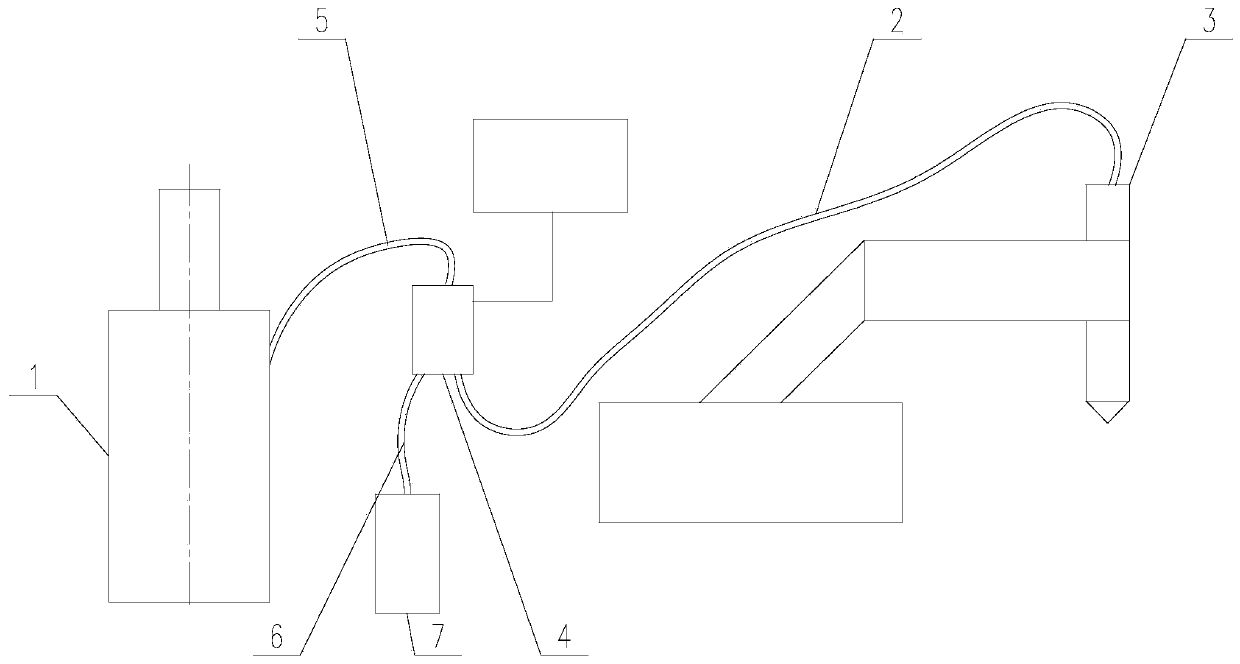
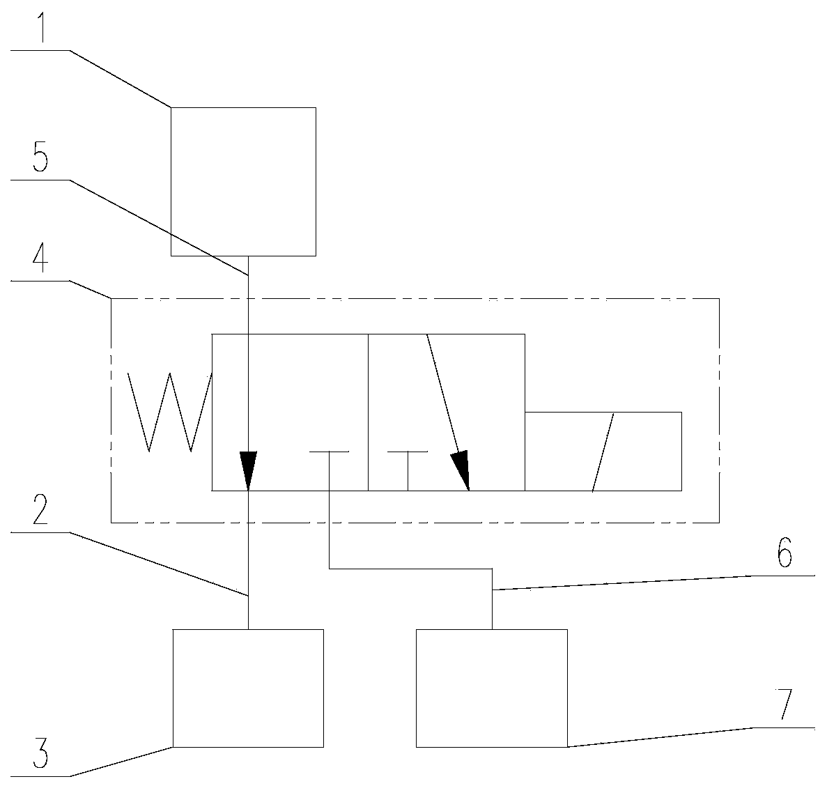
[0035] Such as Figure 1 to Figure 4 As shown, a powder feeding control and recovery device of the present invention includes a powder feeding device 1, the discharge end of the powder feeding device 1 communicates with the laser cladding operation end 3 through a powder feeding pipe 2, and in the powder feeding pipe 2 and the discharge end of the powder feeding device 1 is connected with a powder storage assembly, the powder storage assembly includes a powder inlet pipe 5, a reversing valve 4, a powder outlet pipe 6 and a powder storage tank 7 connected in sequence. Directional valve 4 is a two-position three-way reversing valve, its feed end communicates with the discharge end of powder feeding device 1 through powder inlet pipe 5, and its first discharge end is far away from powder feeding pipe 2 for laser cladding operation One end of end 3 is communicated, and its second discharge end communicates with the feed end of powder storage tank 7 through powder discharge pipe 6,...

Embodiment 2

[0043] This embodiment is to illustrate the specific implementation structure of the powder storage tank 7 in the first embodiment.

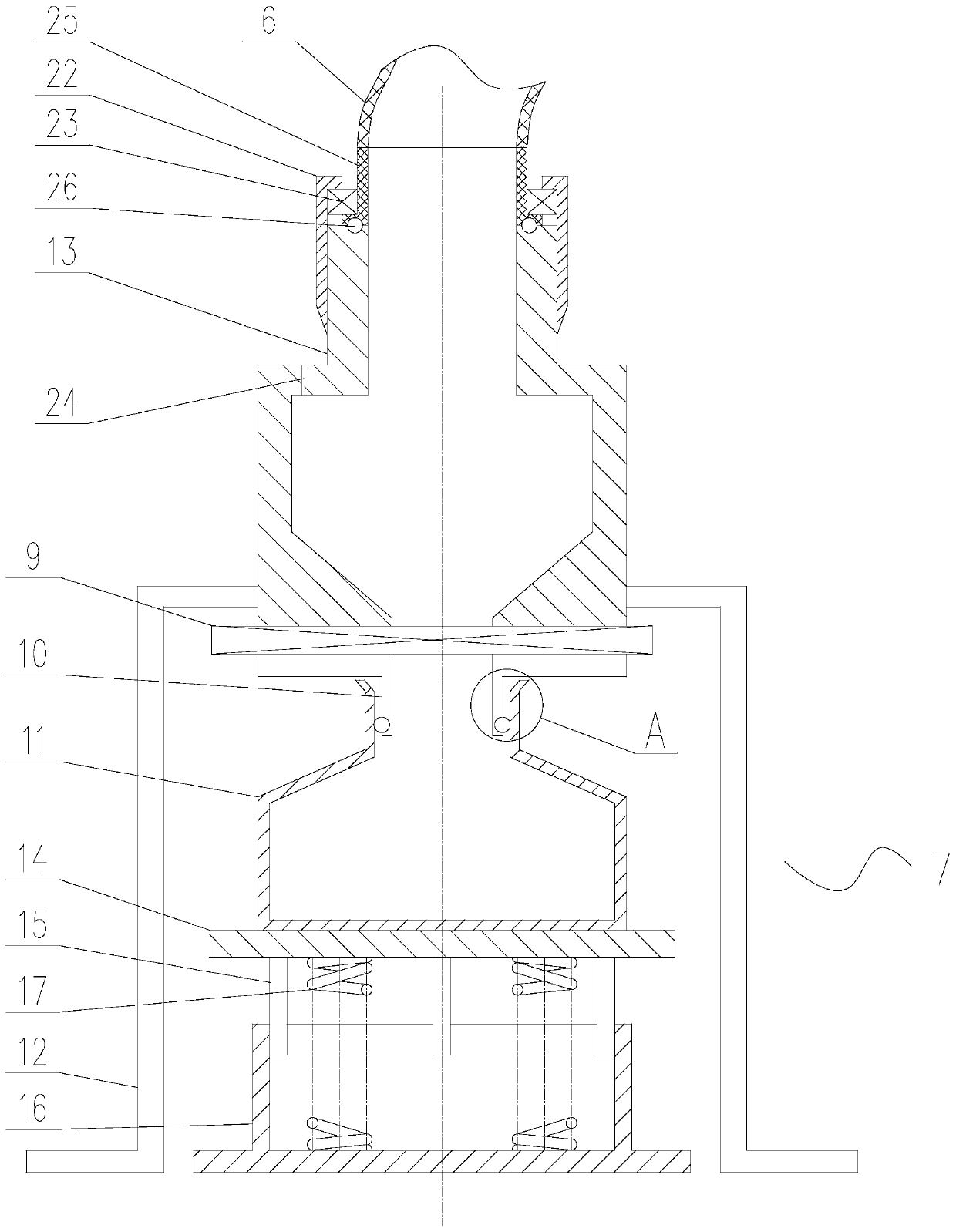
[0044] Such as image 3 As shown, in the present invention, the powder storage tank 7 includes a tank body 8, a butterfly valve 9, a guide pipe 10, a moving tank 11 and a lifting support platform arranged sequentially from top to bottom, and the tank body 8, the butterfly valve 9 and the guide tube The connecting pipes 10 are connected in sequence, and the butterfly valve 9 controls the on-off of the inner cavity of the tank body 8 and the central hole of the connecting pipe 10. The tank body 8 is supported on the ground by a plurality of supporting legs 12, and a row is arranged on the upper side of the tank body 8. Air hole 24, the air vent is a small-diameter hole, which is used to maintain the pressure balance inside and outside the tank body 8 during the operation of collecting powder. The top of the tank body 8 protrudes into a connecting ...

Embodiment 3

[0053] This embodiment is about the specific implementation structure of the lifting support platform in the second embodiment.

[0054] Such as image 3 As shown, in the present invention, the lifting support platform includes a base plate 14, a guide shaft 15, a support cylinder 16 and a spring 17, the base plate 14 is horizontally arranged, and the moving tank 11 is located on its upper surface, and the guide shaft 15 has many One, its axis is parallel to the axis of the support cylinder 16, and it is distributed symmetrically along the axis of the support cylinder 16, its top is connected with the bottom plate 14, its bottom is inserted in the center hole of the support cylinder 16, and the cylinder of the guide shaft 15 The side wall is inscribed in the central hole of the support cylinder 16 .

[0055] The spring 17 is located in the center hole of the support tube 16, and its upper and lower ends are respectively in contact with the lower surface of the bottom plate 14...


PUM


Abstract

The invention discloses a powder feeding control and recovery device. The powder feeding control and recovery device comprises a powder feeding device, wherein the discharge end of the powder feedingdevice communicates with a laser cladding operation end through a powder feeding pipe; a powder storage assembly is connected between the powder feeding pipe and the discharge end of the powder feeding device; the powder storage assembly comprises a powder inlet pipe, a reversing valve, a powder outlet pipe and a powder storage tank which are sequentially communicated; the reversing valve is a two-position three-way reversing valve; the feed end of the reversing valve communicates with the discharge end of the powder feeding device through the powder inlet pipe; the first discharge end of thereversing valve communicates with one end, far away from the laser cladding operation end, of the powder feeding pipe; and the second discharge end of the reversing valve communicates with the feed end of the powder storage tank through the powder outlet pipe. According to the powder feeding control and recovery device, the powder stabilization reservation time is avoided, the time cost is reduced, and real-time control is realized; powder in the powder storage tank can be fed back to the powder feeding device for cladding welding operation, so that powder waste is prevented, and the raw material cost is reduced; and the stability of the powder conveying amount is guaranteed, and the adverse effect of processing suspension on the powder stability is eliminated.

Description

technical field [0001] The invention relates to the technical field of additive manufacturing, in particular to a powder feeding control and recovery device. Background technique [0002] Additive manufacturing technology refers to the "printing" of powder materials on the surface of objects to form the required surface layer or directly form the desired object, such as 3D printing, cladding equipment, etc. On the related equipment of additive manufacturing, it is necessary to use the powder bucket to load the printing powder required for printing to facilitate subsequent printing operations. [0003] In the welding and laser additive manufacturing system, the powder is delivered to the operation end through the powder feeding device, that is, the cladding head of the laser cladding welding equipment, and the powder amount can be adjusted through the powder feeding device as needed. During welding or laser processing, it is not continuous, and there is often a pause in the ...

Claims


Application Information

Patent Timeline
Patent Type & Authority Applications(China)
IPC IPC(8): B29C64/321B29C64/255B29C64/357B33Y30/00B33Y40/00
CPCB29C64/321B29C64/255B29C64/357B33Y30/00B33Y40/00
Inventor 周超彭柏元阳义何浩
Owner 成都青石激光科技有限公司
Why Eureka
Try Eureka