Fluidization device for powder tank-type container

A fluidization device and container technology, applied in the field of powder material transportation equipment, can solve the problems of not being able to fully utilize the space in the tank and not being able to obtain transportation efficiency, so as to improve the unloading efficiency, increase the effective volume, and increase the fluidization area effect

Pending Publication Date: 2020-07-31
靖江市亚泰物流装备有限公司
View PDF0 Cites 2 Cited by
  • Summary
  • Abstract
  • Description
  • Claims
  • Application Information

AI Technical Summary

Problems solved by technology

This traditional fluidization device cannot make full use of the space in the tank and cannot obtain ideal transportation efficiency

Method used


Image

  • Fluidization device for powder tank-type container
  • Fluidization device for powder tank-type container
  • Fluidization device for powder tank-type container

Examples


Embodiment 1

[0037] In this embodiment of the application:

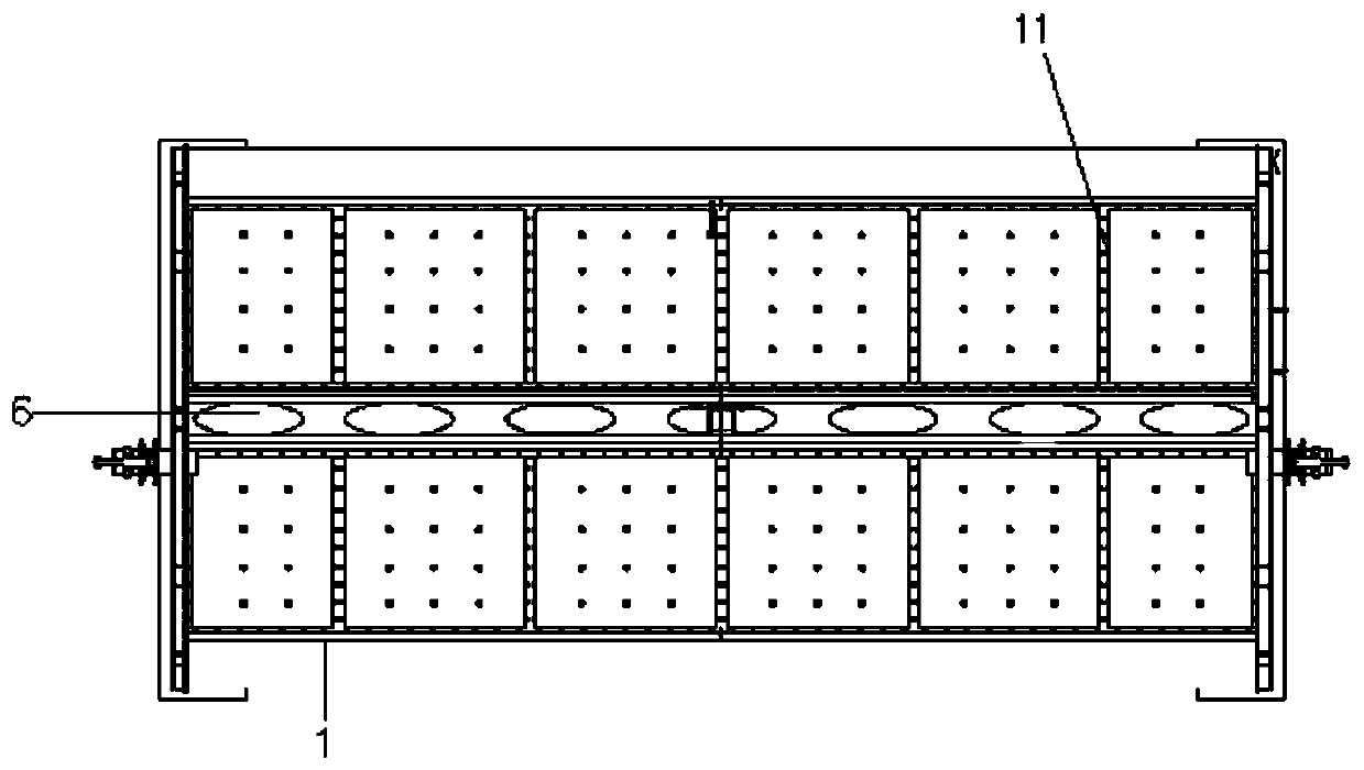
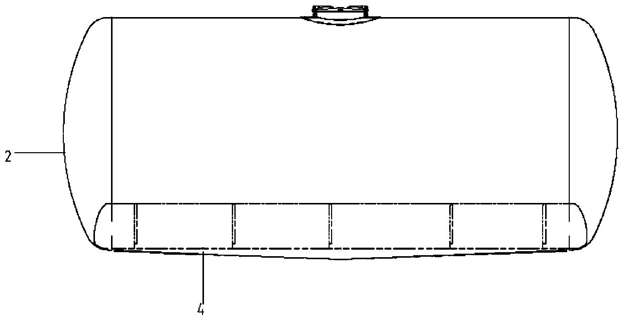
[0038] Such as Figure 1-5 As shown, a fluidization device for a powder tank container includes: a cylinder body 1, a head at both ends of the cylinder body 1, two sets of left and right fluidized beds 3, and a fluidized bed 3 below There is a longitudinal guide fluid 4, the fluidized bed 3 extends longitudinally along the cylinder 1, the fluidized bed 3 is arranged inside the cylinder 1, between the fluidized bed 3 and the cylinder 1 The air chamber structure 5 is formed. The left and right sets of fluidized beds 3 are inclined structures, the upper end of the fluidized bed 3 is connected to the side of the cylinder 1, and the lower end of the fluidized bed 3 is connected to the bottom of the cylinder.

[0039] In this embodiment, the left and right two sets of fluidized beds 3 have the effects of fluidization and diversion at the same time.

[0040] Furthermore, the fluidized bed 3 has an inclined arc structure, the maximum vertical...

Embodiment 2

[0050] In this embodiment of the application:

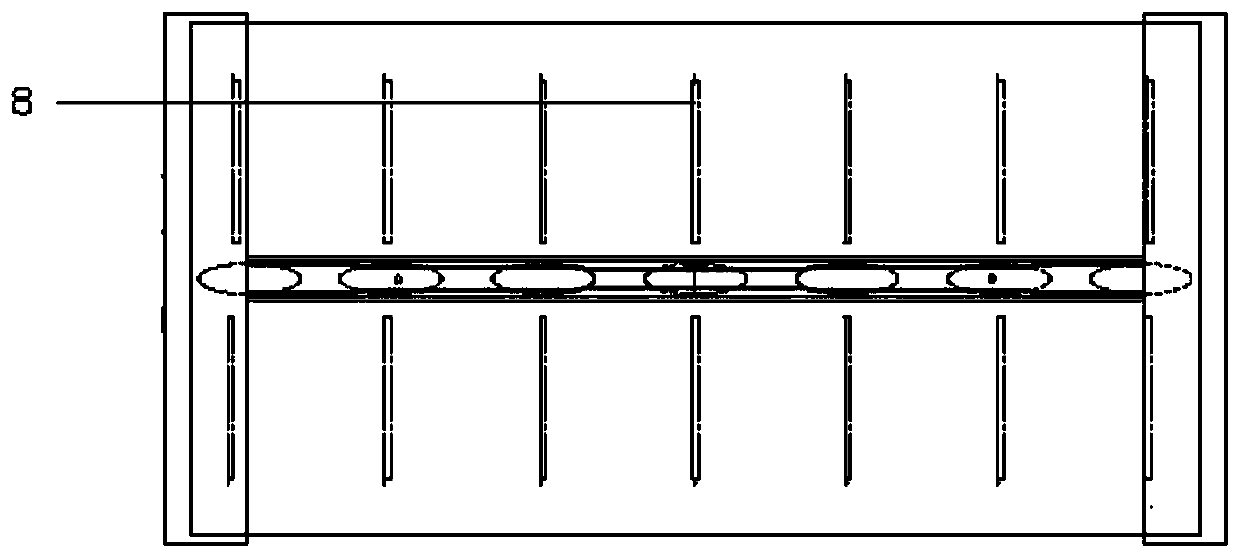
[0051] Such as Figure 1-2 , Image 6 , Figure 7 As shown, a fluidization device for a powder tank container includes: a cylinder body 1, a head at both ends of the cylinder body 1, two sets of left and right fluidized beds 3, and a longitudinal guide fluid is arranged below the fluidized bed 3 4. The fluidized bed 3 extends longitudinally along the cylinder 1. The fluidized bed 3 is arranged inside the cylinder 1. An air chamber structure 5 is formed between the fluidized bed 3 and the cylinder 1, and the upper end of the fluidized bed 3 is connected to the cylinder 1. side.

[0052] The fluidized bed 3 includes a porous plate 9, a gas-permeable layer 10, and a compression device 11. The gas-permeable layer 10 is laid on the porous plate 9, and the gas-permeable layer 10 is fixed on the porous plate 9 by the compression device 11. Fasteners are fixed.

[0053] The difference from Example 1 is that the fluidized bed 3 has an incline...

Embodiment 3

[0062] In this embodiment of the application:

[0063] Such as Figure 1-5 As shown, a fluidization device for a powder tank container includes: a cylinder body 1, a head provided at both ends of the cylinder body 1, two sets of left and right fluidized beds 3, and a longitudinal guide fluid below the fluidized bed 3 4. The fluidized bed 3 extends longitudinally along the cylinder 1. The fluidized bed 3 is arranged inside the cylinder 1. An air chamber structure 5 is formed between the fluidized bed 3 and the cylinder 1, and the upper end of the fluidized bed 3 is connected to the cylinder 1. On the side, the lower end of the fluidized bed 3 is connected to the bottom of the cylinder.

[0064] Further, the fluidized bed 3 has an inclined arc structure, the maximum vertical distance between the fluidized bed 3 and the cylinder 1 is 50 cm, and the included angle between the fluidized bed 3 and the cylinder 1 is 22.5°.

[0065] Furthermore, the bottom of the cylinder 1 is provided with...


PUM


Abstract

The invention provides a fluidization device for a powder tank-type container, and belongs to the field of transport equipment for particle materials. The invention provides a fluidization device fora powder tank-type container. The fluidization device for the powder tank-type container comprises a barrel body, sealing heads arranged at the two ends of the barrel body, and at least one group of fluidization beds, wherein a longitudinal flow guide body is arranged below the fluidization beds; the fluidization beds extend in the longitudinal direction of the barrel body; the fluidization beds are arranged in the barrel body; and an air chamber structure is formed between the fluidization beds and the barrel body. The invention provides a fluidization device for a powder tank-type container.The effects of fluidization and flow guide are acted simultaneously through the design of a fluidization bed structure, the in-tank effective volume is furthest increased, and moreover, the unloadingefficiency is increased.

Description

Technical field [0001] The application belongs to the field of powder material transportation equipment, and relates to a fluidization device of a powder material tank container. Background technique [0002] At present, the tank trucks for bulk cement and powder materials on the market are usually suitable for certain specific materials, with single function and easy to overweight. In order to meet the growing market demand, more customers choose tank containers instead of tank trucks to transport cement, Powder and other materials. In order to make the discharge rate high and the residual volume low, most tank containers adopt the method of setting side deflectors and air chamber structure. This traditional fluidization device cannot make full use of the space in the tank and cannot achieve ideal transportation efficiency. Summary of the invention [0003] (1) Technical problems to be solved [0004] In view of the above technical problems, this application provides a fluidizat...

Claims


Application Information

Patent Timeline
Patent Type & Authority Applications(China)
IPC IPC(8): B65D90/00
CPCB65D90/00
Inventor 杨正华霍海波朱健朱剑徐贝鞠露
Owner 靖江市亚泰物流装备有限公司
Why Eureka
Try Eureka