Electric control piston oil injection cooling system and working method thereof

An oil-injection cooling and piston technology, applied in the field of electronically controlled piston oil-injection cooling system, can solve the problems of ineffective use of the internal cooling oil cavity for cooling, insufficient oil cooling area, and inability to cool the bottom of the piston, so as to improve power performance and economy. performance, optimized cooling, smooth cold start

Pending Publication Date: 2020-07-31
HEBEI UNIV OF TECH
View PDF0 Cites 7 Cited by
  • Summary
  • Abstract
  • Description
  • Claims
  • Application Information

AI Technical Summary

Problems solved by technology

[0003] In the prior art, the oil spraying method in which the cooling oil is sprayed vertically upwards into the internal cooling oil chamber of the piston through the oil nozzle cannot effectively cool the bottom of the piston; or the oil spraying method directly using a single nozzle to spray upwards can not effectively use the internal cooling oil chamber The two methods have the problems of insufficient oil cooling area and low cooling efficiency respectively.

Method used


Image

  • Electric control piston oil injection cooling system and working method thereof
  • Electric control piston oil injection cooling system and working method thereof
  • Electric control piston oil injection cooling system and working method thereof

Examples


Embodiment Construction

[0028] Below, by referring to the accompanying drawings, the embodiment of the present invention will be described in further detail through the description of the embodiments, in order to help those skilled in the art to have a more complete, accurate and in-depth understanding of the concept and technical solutions of the present invention, and to help on its implementation.

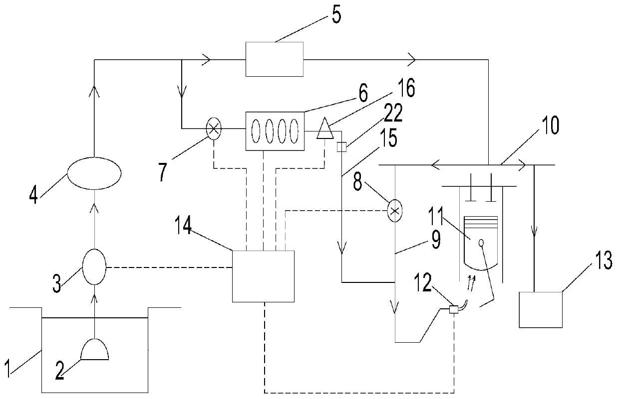
[0029] Such as figure 1 , the present invention provides an electronically controlled piston fuel injection cooling system, comprising a variable displacement electronically controlled oil pump 3, an oil injection nozzle 12, an oil filter 2 connected to a variable displacement electronically controlled oil pump 3, and a variable displacement electronically controlled machine The outlet of the oil pump 3 is connected to the oil filter 4, and the oil filter enters the main oil passage 10 through the oil cooler 5, and a heater connected to the inlet of the oil injector 12 is set between the oil filter 4 a...


PUM


Abstract

The invention discloses an electric control piston oil injection cooling system and a working method thereof. Through a double-oil-injection working mode of an oil injection nozzle at the bottom of apiston, the effect of cooling a cold oil cavity in the piston and the effect of cooling the bottom of the piston are achieved. The double-oil-injection mode of an inner nozzle and an oil injection nozzle outer sleeve is adopted for the oil injection nozzle, a plurality of obliquely upward outer injection holes are distributed in the side face of the tail section of the oil injection nozzle outer sleeve in the circumferential direction, and the multiple outer injection holes form an outer annular nozzle. A heating oil channel connected with an inlet of the oil injection nozzle is arranged between an oil filter and an oil cooler, an oil heater is installed in the heating oil channel, a hot electromagnetic valve switch is installed on a pipeline close to an inlet of the oil heater, an auxiliary oil channel is arranged at the connecting position of the oil heater and the inlet of the oil injection nozzle and connected to a main oil channel, and a cold electromagnetic valve switch is installed on the auxiliary oil channel. According to the electric control piston oil injection cooling system and the working method thereof, lubricating oil injection of the cold oil cavity in the piston and lubricating oil injection of the bottom of the piston can be achieved, the lubricating condition of the piston and a cylinder sleeve during cold starting is improved, and the heat efficiency of aninternal combustion engine is improved.

Description

Technical field: [0001] The invention belongs to the technical field of internal combustion engines. Specifically, the invention relates to an electronically controlled piston fuel injection cooling system and a working method thereof. Background technique: [0002] When the internal combustion engine is working, friction occurs between the surfaces of the moving parts due to the relatively high-speed motion. If the metal surface is directly rubbed, it will not only increase the internal power loss of the internal combustion engine, but also cause the friction surface to wear rapidly. At the same time, the large amount of heat generated by the friction will cause the working surface of some parts to melt, causing the internal combustion engine to fail to work normally. In order to ensure the normal operation of the internal combustion engine, it is necessary to lubricate the surfaces of the relative moving parts to form a lubricating oil film between the parts and change dir...

Claims


Application Information

Patent Timeline
Patent Type & Authority Applications(China)
IPC IPC(8): F01P3/08F01M5/02F01M11/03
CPCF01M5/021F01M11/03F01P3/08F01P2003/006
Inventor 刘晓日王宝磊徐晓宇华超李孟涵
Owner HEBEI UNIV OF TECH
Why Eureka
Try Eureka