A kind of air intake pipe applied to centrifugal fan

A technology of centrifugal fan and air intake pipe, which is applied in the application, components of the pumping device for elastic fluid, wind power engine, etc., and can solve the problem that the fan is difficult to clean and so on

Active Publication Date: 2021-04-30
SAYI ELECTRICAL APPLIANCE CO LTD
View PDF7 Cites 0 Cited by
  • Summary
  • Abstract
  • Description
  • Claims
  • Application Information

AI Technical Summary

Problems solved by technology

[0005] The purpose of the present invention is to solve the problem that the above-mentioned live mosquitoes enter the ventilation duct or even the inside of the ventilator, which will affect the use of the ventilator and are difficult to clean, and provide a kind of air intake duct for centrifugal ventilators that kills live mosquitoes and automatically cleans them at the same time

Method used


Image

  • A kind of air intake pipe applied to centrifugal fan
  • A kind of air intake pipe applied to centrifugal fan
  • A kind of air intake pipe applied to centrifugal fan

Examples


Embodiment 1

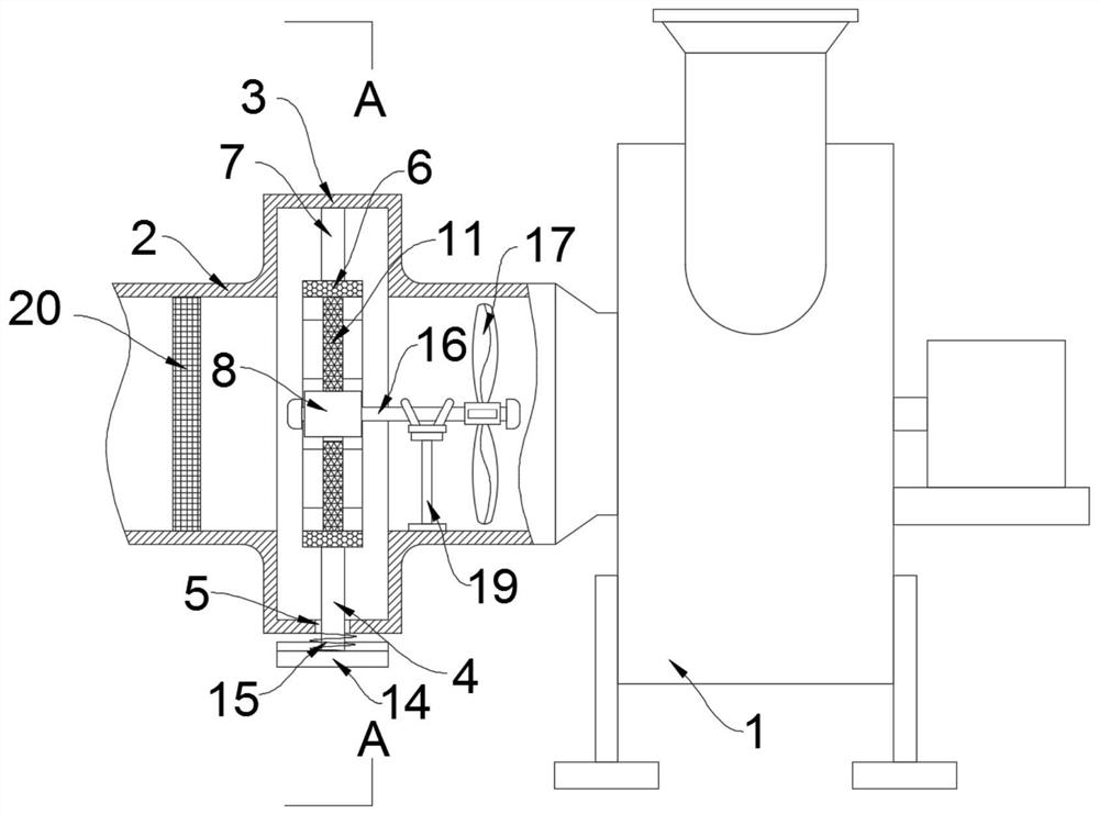
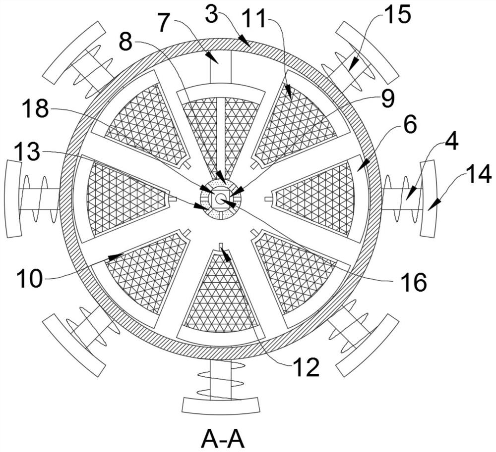
[0024] Such as Figure 1-3 As shown, a kind of air intake pipe applied to a centrifugal fan includes an air inlet pipe 2 fixedly connected to the air inlet of the centrifugal fan 1, and an expansion ring 3 is arranged on the side wall of the air inlet pipe 2, and the diameter of the expansion ring 3 is larger than The diameter of the air inlet pipe 2, the side wall of the expansion ring 3 is slidingly connected with a plurality of sliding rods 4, the side wall of the expansion ring 3 is provided with a sliding groove 5 matching the sliding rod 4, and the sliding rod 4 is located inside the expansion ring 3 One end of the connecting block 6 is fixedly connected with an arc-shaped connecting block 6, and one end of a plurality of connecting blocks 6 close to the center of the expansion ring is fixedly connected with a fan-shaped frame 10, the fan-shaped frame 10 is fixedly connected with a power grid 11, and the upper end of the fan-shaped frame 10 is fixedly connected with a Co...

Embodiment 2

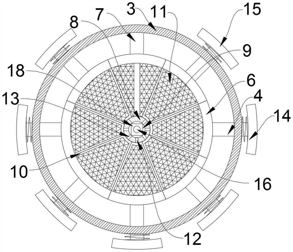
[0032] Such as Figure 4 As shown, the difference between this embodiment and Embodiment 1 lies in that the sliding sleeve on the outermost side of the sliding rod 4 is provided with a wedge block 21 arranged obliquely, and the wedge block 21 is fixedly connected with the inner wall of the expansion ring 3 .

[0033] In this embodiment, a discharge port 22 is formed on the expansion ring 3 at a position corresponding to the lower end of the wedge block 21 , and a loading box 23 is provided at a position corresponding to the discharge port 22 on the outer wall of the expansion ring 3 .

[0034] The setting of the wedge block 21, after the impurities and residues are knocked down, accumulate on the wedge block 21 at the inner bottom of the expansion ring 3, due to the inclined setting of the wedge block 21, the impurities and residues slide down along the wedge block 21 to the discharge port 22 And enter the inside of the loading box 23, and only need to disassemble the loading ...


PUM


Abstract

The invention belongs to the field of ventilator-related equipment, and in particular relates to an air intake pipe applied to a centrifugal fan, comprising an air intake pipe fixedly connected to the air inlet end of the centrifugal fan, and an expansion ring is arranged on the side wall of the air intake pipe to expand There are multiple sliding rods running through the sliding connection on the side wall of the ring. The end of the sliding rod inside the expansion ring is fixedly connected with an arc-shaped connecting block. The uppermost connecting block is fixedly connected with the inner top surface of the expansion ring through the fixing rod. The drive box is fixedly connected to the lower end, the fan-shaped frame is fixedly connected to the end of the connection block close to the center of the expansion ring, the power grid is fixedly connected to the fan-shaped frame, the upper end of the fan-shaped frame is fixedly connected to a conductive column, and the side wall of the drive box is provided with a conductive column. Matching through slot, the drive box is equipped with a power generating mechanism. The invention can prevent the exhausted air from being mixed with peculiar smell caused by live mosquitoes entering the ventilator through the air intake pipe during the working period of the ventilator by setting the power grid, and at the same time ensure the service life of the ventilator.

Description

technical field [0001] The invention belongs to the field of ventilator-related equipment, and in particular relates to an intake pipe applied to a centrifugal ventilator. Background technique [0002] Nowadays, almost all shopping malls and office spaces are equipped with ventilation systems, the purpose of which is to ensure the air circulation and freshness of the air in the space, avoid insufficient air supply due to the high sealing of the internal space when people gather, and effectively reduce the Small probability of airborne transmission of the virus after the emergence of a carrier of the pathogen. [0003] The general ventilation pipes are equipped with screens or at the ports, but due to the existence of a large number of mosquitoes in the air, especially in summer, a large number of mosquitoes are sucked into the intake pipe when the ventilation pipes are in the intake state, even if there are screens in the ventilation pipes. However, due to the activity of t...

Claims


Application Information

Patent Timeline
Patent Type & Authority Patents(China)
IPC IPC(8): F04D29/42F04D29/70F04D29/00F03D9/25F03D9/30A01M1/22
CPCA01M1/223F04D29/002F04D29/4206F04D29/701F03D9/25F03D9/30Y02E10/72Y02E10/728
Inventor 雷帅
Owner SAYI ELECTRICAL APPLIANCE CO LTD
Why Eureka
Try Eureka