Crane rotation buffer reversing valve and crane open type rotation brake control system

A technology of slewing buffer and crane, which is applied in the direction of cranes, multi-way valves, valve devices, etc., can solve the problems of pressure oil leakage, high sensitivity of hydraulic oil temperature, rising and rising to overload valve pressure, etc., so as to improve reliability , simple structure, good effect of pressure relief and pressure building speed

Pending Publication Date: 2020-07-31
ANHUI LIUGONG CRANE
View PDF0 Cites 1 Cited by
  • Summary
  • Abstract
  • Description
  • Claims
  • Application Information

AI Technical Summary

Problems solved by technology

[0005] 1. The damping cannot be made small enough. Generally, it is difficult to achieve a damping hole below 0.4 due to cleanliness and other reasons, so it cannot be delayed for a long enough time
[0006] 2. Due to the weather, the crane needs to operate in different temperature environments. The hydraulic oil has a high sensitivity to temperature, which leads to a large change in the viscosity of the hydraulic oil and a large impact on the delay characteristics of the damping.
Also seriously affect the braking effect
[0007] 3. With the deterioration of the cleanliness of the hydraulic oil of the whole machine, the probability of the damping hole being blocked by pollution increases, causing the pressure oil in the brake 3a to leak slowly until it is completely blocked, resulting in a rotary slide
[0008] 4. Since the reversing valve adopts the closed-center switch valve design, the rotary valve only communicates with the P port and the T port when it is opened and closed. Once the reversing port P port pressure oil directly enters the A port and B port of the motor 2a due to the large load due to the moment of inertia For larger reasons, the pressure will rise instantaneously and reach the pressure of the overload valve, causing an impact

Method used


Image

  • Crane rotation buffer reversing valve and crane open type rotation brake control system
  • Crane rotation buffer reversing valve and crane open type rotation brake control system
  • Crane rotation buffer reversing valve and crane open type rotation brake control system

Examples


Embodiment Construction

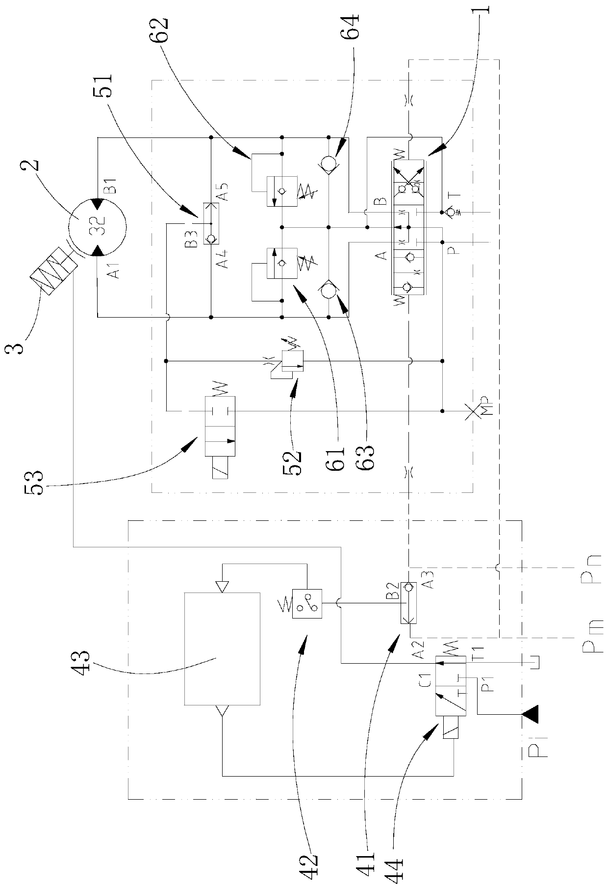
[0035] Such as Figures 2 to 3 shown

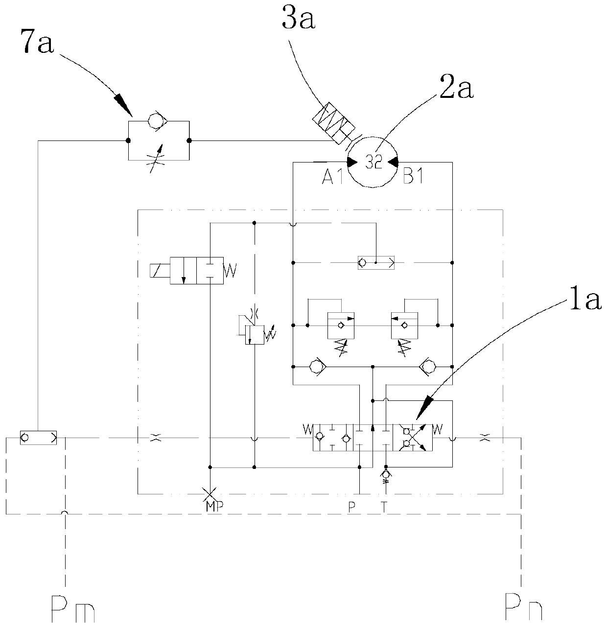
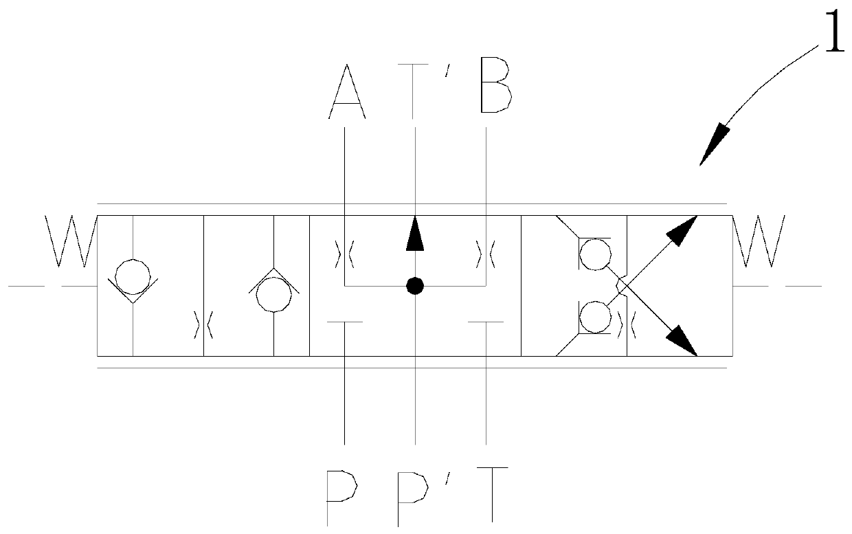
[0036]The crane slewing buffer reversing valve 1 is a three-position six-way valve. The crane slewing buffer reversing valve 1 has a first reversing port A, a second reversing port B, an oil inlet P, an oil return port T, a first The unloading port P' and the second unloading port T', the oil inlet P and the first unloading port P' are respectively connected to the rotary oil source, and the oil return port T and the second unloading port T' are respectively connected to the oil tank;

[0037] The crane slewing buffer reversing valve 1 has a neutral position, a first working position and a second working position. The unloading ports T' are respectively connected, and the passage between the first unloading port P' and the first reversing port A is a throttling passage (the aperture of the throttling passage is smaller than the aperture of the normal passage, and the flow rate of the throttling passage is smaller than that of the normal ...


PUM


Abstract

The invention provides a crane rotation buffer reversing valve. In the middle position, a first unloading port communicates with a first reversing port through a throttling passage, and a second unloading port communicates with a second reversing port through a throttling passage; in the first working position, the first reversing port communicates with an oil inlet, and the second reversing portcommunicates with an oil return port; in the second working position, the second reversing port communicates with the oil inlet, and the first reversing port communicates with the oil return port; andin the three states, the first unloading port communicates with the second unloading port. Along with reversing, opening of the oil return port is reduced, and rising of the load pressure is weakened. The invention further provides a crane open type rotation brake control system. The crane open type rotation brake control system comprises a reversing valve, a motor, a brake and a brake control unit. An oil inlet of a first shuttle valve of the brake control unit communicates with a pilot control oil source, an oil outlet of the first shuttle valve communicates with a pressure switch control oil port, a pressure switch triggers a delay relay, and the delay relay controls an electromagnetic reversing valve. The two reversing ports of the reversing valve are connected with two working oil ports of the motor.

Description

technical field [0001] The invention relates to a reversing valve used in a slewing mechanism of a crane. [0002] The invention also relates to a crane open type slewing braking control system. Background technique [0003] Modern medium and large-tonnage cranes generally use hydraulically driven crane slewing control. Due to the large mass and inertia of the crane's upper car turntable boom and components, there are start and stop impacts during the slewing operation that seriously affect the customer's slewing performance. Therefore, in order to reduce similar shocks, the general Improve the swing opening speed and the closing time of the brake 3a, such as figure 1 As shown, when the brake 3a (opens and closes, but because the hydraulic system itself wants to produce a delay, it needs to be realized by restricting the damping, for example, the form of the one-way damping valve 7a is used to realize when the experiment is fast-opening and slow-closing, and because the rev...

Claims


Application Information

Patent Timeline
Patent Type & Authority Applications(China)
IPC IPC(8): F15B13/02F16K11/00B66C23/86B66D5/26
CPCB66C23/86B66D5/26B66D2700/035F15B13/02F16K11/00
Inventor 徐莉王开宇朱庆轩徐青山王充
Owner ANHUI LIUGONG CRANE
Why Eureka
Try Eureka