
A flow element measurement method of river flow during ice-covered period

A technology of flow rate and flow element, which is applied in the directions of full-field flow measurement, flow/mass flow measurement, fluid velocity measurement, etc. It can solve the problems of inability to observe the flow under the ice continuously for a long time, high cost of manpower and material resources, and engineering and technical personnel falling into the water, etc. , to reduce the risk of personal accidents, improve observation accuracy, and reduce the number of drilling holes

Active Publication Date: 2021-03-02
CHINA INST OF WATER RESOURCES & HYDROPOWER RES
View PDF4 Cites 0 Cited by
  • Summary
  • Abstract
  • Description
  • Claims
  • Application Information

AI Technical Summary

Problems solved by technology

However, this method has the following defects: firstly, drilling holes on the ice sheet is not safe during the initial sealing period and the ice melting period, and it is very easy to cause engineering and technical personnel to fall into the water, which is easy to cause accidents; It is difficult to measure flow continuously by punching holes, and the measurement efficiency is low; the third is that the manpower and material cost of flow measurement during glacial period are high, and it is impossible to observe the flow under the ice continuously for a long time and with multiple sections.
However, this method only simplifies the flow measurement work at each ice hole, and still needs to arrange different ice holes along the section. The workload of flow measurement under ice is heavy, and the difficulty and danger still exist.

Method used


Image

  • A flow element measurement method of river flow during ice-covered period
  • A flow element measurement method of river flow during ice-covered period
  • A flow element measurement method of river flow during ice-covered period

Examples


Embodiment

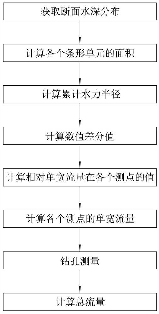
[0043] This embodiment is a method for measuring the flow rate under the ice sheet by using the flow element. The specific steps of the method are as follows, and the process is as follows figure 1 Shown:

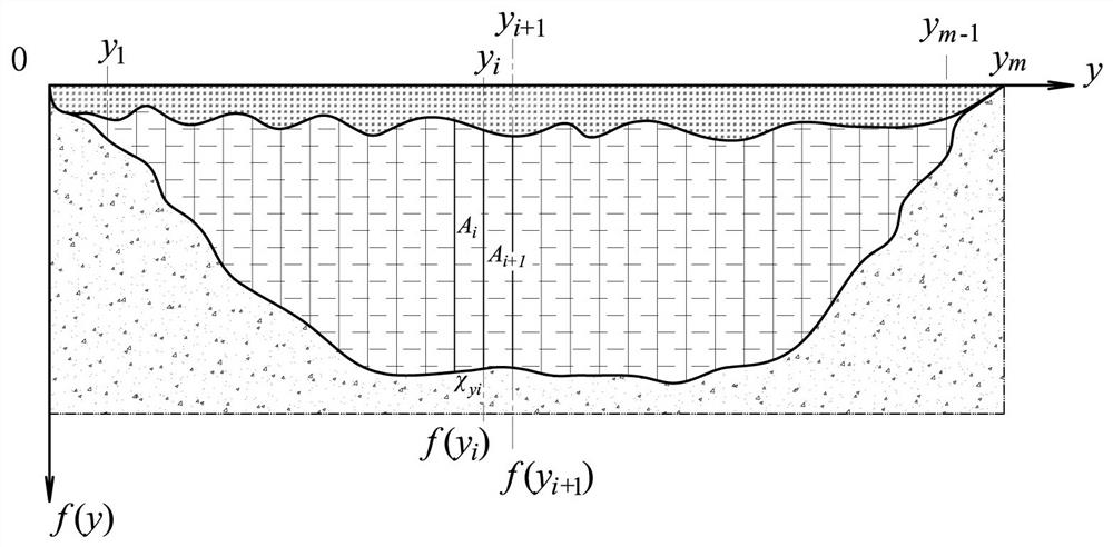
[0044] Step 1, obtain the water depth distribution of the section: select multiple cross sections on the measured river section, divide the cross section into m-1 bar units, and record the water depth distribution at m measuring points.

[0045] The river section to be measured is generally a river section prone to ice dams, and the length is usually tens of kilometers. The tens of kilometers are divided into multiple cross-sections perpendicular to the flow direction, and the average distance between each cross-section is several thousand meters. . After the cross-section is selected, divide each cross-section into m-1 strip units from the bottom of the ice layer to the river bed. Each strip unit is arranged side by side from one side of the river bank to the other side,...


PUM


Abstract

The invention relates to a flow element measurement method for the flow of a river during the ice-covered period, comprising: obtaining the water depth distribution of the section; calculating the area of ​​each strip unit; calculating the cumulative hydraulic radius; calculating the numerical difference value; calculating the relative single-width flow at each measuring point value; calculate the single-width flow of each measuring point; borehole measurement; calculate the total flow. The calculation method of the invention greatly optimizes the under-ice drilling method for flow measurement, and reduces the number of drilling holes on the ice sheet. Compared with the traditional porous multi-point flow velocity measurement method, the present invention only needs to measure the flow velocity at two points, which effectively reduces the workload of measurement, reduces the measurement cost under low temperature and bad weather, shortens the time of flow measurement, and reduces the The risk of personal accidents of skilled workers has greatly improved the efficiency of underglacial flow measurement of northern rivers. The reduction in the number of boreholes on the ice sheet is conducive to maintaining the flow velocity distribution and flow state of natural rivers under the ice, reducing the external interference introduced by the measurement, and improving the observation accuracy.

Description

technical field [0001] The invention relates to a flow element measurement method for the flow of a river during ice-covered periods, which is a calculation and analysis method for water conservancy projects, and is used for flow observation and water-level-flow relationship analysis of partly or completely ice-covered rivers in the north. Background technique [0002] The rivers in northern China are all faced with the influence of seasonal ice cap closures. The existence of ice caps significantly increases the overall resistance of the river channel, which in turn affects the cross-sectional flow velocity distribution, water level and flow relationship, and river channel flow capacity. For example, in the Yellow River, there are about 110 days of ice-covered periods every year, while the average ice-covered period in Heilongjiang is as long as 160-180 days. The relationship between water level and flow under the traditional open channel flow of each hydrological station ca...

Claims


Application Information

Patent Timeline
Patent Type & Authority Patents(China)
IPC IPC(8): G01F1/00G01C13/00G01P5/00
CPCG01C13/00G01F1/002G01P5/001
Inventor 潘佳佳郭新蕾王涛付辉余弘婧李甲振雷添杰郭永鑫施春蓉路锦枝杨涛
Owner CHINA INST OF WATER RESOURCES & HYDROPOWER RES
Learn More