Mining overburden rock motion law in-situ observation drill hole layout method

A technology of drilling layout and movement rules, applied in the direction of optical exploration, etc., can solve the problems of high cost, scrapped drilling, waste of engineering time and project funds, etc., to reduce the initial engineering investment, reduce the number of drilling holes, and reduce the initial investment small effect

Active Publication Date: 2016-08-31
CHINA UNIV OF MINING & TECH
View PDF6 Cites 8 Cited by
  • Summary
  • Abstract
  • Description
  • Claims
  • Application Information

AI Technical Summary

Problems solved by technology

However, the layout of ground drilling in the traditional method is blind and random to a certain extent, and the number of drilling operations is large, and the cycle is long, the cost is high, and multiple measuring points in the hole will interact with each other. The phenomenon of scrapping, serious waste of engineering time and engineering funds

Method used


Image

  • Mining overburden rock motion law in-situ observation drill hole layout method
  • Mining overburden rock motion law in-situ observation drill hole layout method
  • Mining overburden rock motion law in-situ observation drill hole layout method

Examples


Embodiment Construction

[0019] Below in conjunction with accompanying drawing, the implementation case of the present invention is described further:

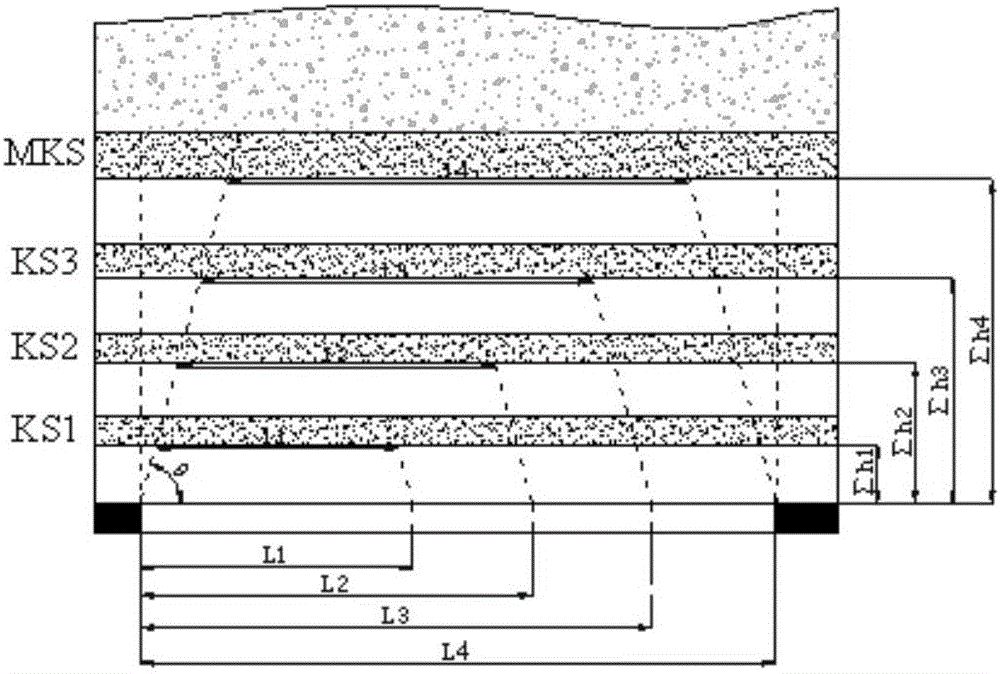
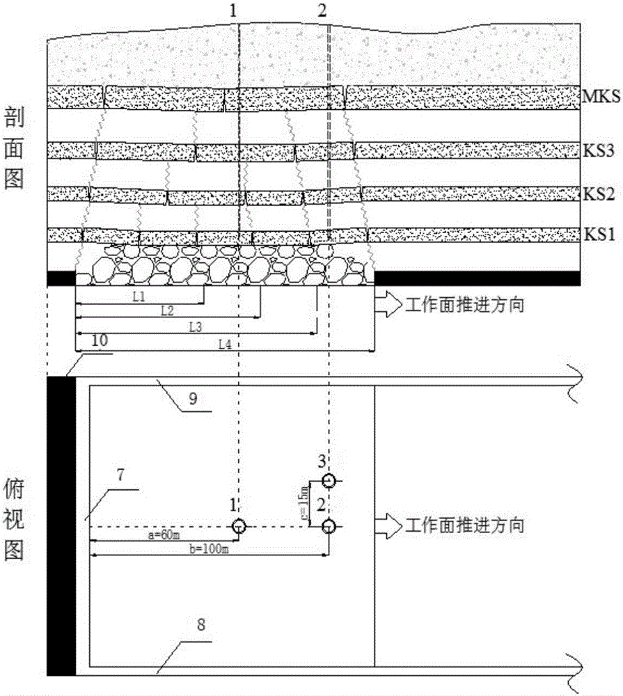
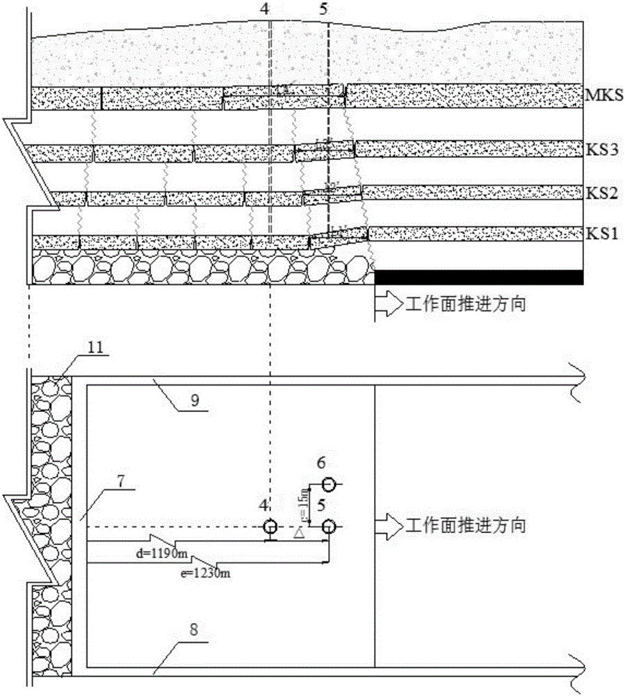
[0020] Such as figure 1 , figure 2 with image 3 As shown, the in-situ observation drilling arrangement method for mining overlying rock movement law of the present invention, its steps are as follows:

[0021] a. Collect the geological information of the mining area, obtain the full columnar strata in this area, use the key layer theory of rock strata movement, obtain the position and related parameters of the key layer of the overlying rock in the full columnar overlying rock, and use the formula: Calculate the limit span l of the key layer of overlying rock i ;using the formula: Calculate the primary breaking distance L of the key layer of overlying rock i ; using the formula Calculate the periodic breaking distance L of the key layer of overlying rock i '; in the formula: the value of i is i=1, 2, 3, 4, respectively representing the sub...


PUM


Abstract

The invention discloses a mining overburden rock motion law in-situ observation drill hole layout method, which is suitable to be used in the field of mining engineering. The mining overburden rock motion law in-situ observation drill hole layout method comprises the steps of: determining a longitudinal overlapping region of fracture ranges of critical layers of an overburden rock by utilizing a critical layer theory; further determining in-situ observation drill hole layout positions and distance between drill holes at a working surface initial mining stage and a working surface overburden rock periodic fracture period, that is, fracture motion of multiple layers and even all the critical layers of the overburden rock can be observed with the minimal ground drill hole number; and providing a mining overburden rock motion law in-situ observation drill hole layout scheme based on the effect achieve in the step 2. The mining overburden rock motion law in-situ observation drill hole layout method avoids the blindness and randomness of drill hole position determination in a traditional method, greatly improves reliability and utilization rate of ground drill holes for observing a mining overburden rock motion law since the real-time monitoring of the overburden rock multiple critical layer fracture motion can be achieved by a single drill hole, achieves a research target with the minimal ground drill hole number, and ensures the realization of maximum economic benefit.

Description

technical field [0001] The invention relates to a drilling hole arrangement method for observation, and is especially suitable for an in-situ observation drilling hole arrangement method for mining overburden rock movement laws used in the field of mining engineering. Background technique [0002] With the mining of underground coal resources, the surrounding rock in the mining space is deformed and damaged to a certain extent, and the damage of the mining rock mass is prominently manifested as the induction of some mine disasters and the impact on the environment. For example: ① endanger the safety of underground workers and the normal operation of equipment, such as roof caving, mine water inrush; ② mining cracks lead to the loss of groundwater resources, especially in arid areas, aggravating soil desertification; ③ mining subsidence damages the surface Build (structure) buildings. All the hazards mentioned above, such as rock pressure from the stope, development of crack...

Claims


Application Information

Patent Timeline
Patent Type & Authority Applications(China)
IPC IPC(8): G01V8/02
CPCG01V8/02
Inventor 朱卫兵李竹鞠金峰许家林徐敬民
Owner CHINA UNIV OF MINING & TECH
Why Eureka
Try Eureka