Slotting blast hole layout structure for blind raise once well completion and well completion method

A technology for arranging structures and cutting holes, which can be used in sinking, shaft equipment, earthwork drilling and mining, etc. It can solve problems such as difficulty in reaching the design well depth, high blast vibration hazards, long drilling time period, etc., and achieve weakening of the rock mass Damage damage phenomenon, high construction precision, effect of reducing construction time period and excavation cost

Active Publication Date: 2019-05-07
DAYE NONFERROUS METALS +1
View PDF7 Cites 9 Cited by
  • Summary
  • Abstract
  • Description
  • Claims
  • Application Information

AI Technical Summary

Problems solved by technology

[0005] The purpose of the present invention is to solve the problems of long drilling time period, high cost of explosives, great damage of blasting vibration, and difficulty in reaching the depth of the designed well during blastin

Method used


Image

  • Slotting blast hole layout structure for blind raise once well completion and well completion method
  • Slotting blast hole layout structure for blind raise once well completion and well completion method
  • Slotting blast hole layout structure for blind raise once well completion and well completion method

Examples


Embodiment 1

[0029] In this embodiment, the construction in an underground mine whose lithology is above medium hardness is taken as an example to describe in detail, and a field blasting construction is carried out at the level of -485m. The height of the blind raised shaft is designed to be 10m. Its diameter is 2.0 m.

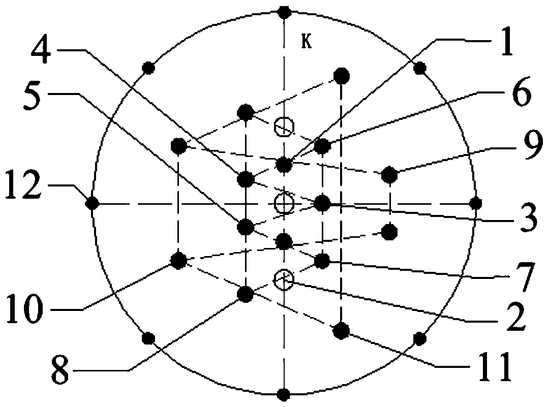
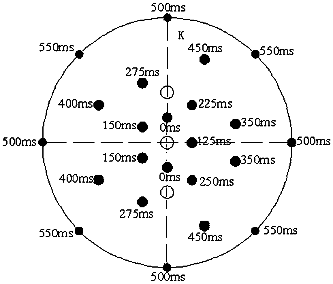
[0030] see figure 1 , the present invention provides a cutting blast hole layout structure for a blind patio well to be formed at one time. A linear cutting hole is provided on one of the center lines K of the blasting area, and the linear cutting hole consists of three empty holes 2 and two Charge holes 1 are alternately arranged.

[0031] The blasting area is provided with a triangular cut hole, and the triangular cut hole consists of a first-level triangular cut hole 3, two second-level triangular cut holes 4 and 5, and two third-level triangular cut holes 6. and 7, two fourth-level triangular cut holes 8, the first-level triangular cut hole 3 is vertically arranged ...

Embodiment 2

[0040] On the basis of Embodiment 1, this embodiment provides a method for forming a blind well at one time, including the following steps:

[0041] Step 1: On the end face of the circular blasting area of ​​the blind patio, use a medium-deep hole drilling rig to drill a linear cut hole along one of the center lines K. Holes and two charge holes are arranged alternately, the distance between each two adjacent linear cut holes is 0.2m, the charge hole diameter is 76mm, and the empty hole diameter is 102mm to form a linear cut hole Arrangement, the depth of the five blastholes is 50-100cm deeper than the height of the designed blind patio;

[0042] Step 2: Drill triangular cut holes on both sides of the center line described in step 1. The aperture of the triangular cut holes is 76mm; Cutting holes, two third-level triangular cutting holes and two fourth-level triangular cutting holes, the first-level triangular cutting holes are vertically set on the side 0.2m away from the ce...


PUM

PropertyMeasurementUnit
Apertureaaaaaaaaaa
Pitchaaaaaaaaaa
Heightaaaaaaaaaa

Abstract

The invention discloses a slotting blast hole layout structure for blind raise once well completion and a well completion method. A plurality of linear slotting holes are formed in a circle center line of a blast area, wherein each linear slotting hole is formed by alternatively laying out an empty hole and an explosive filling hole; a plurality of triangular slotting holes which are arranged at the two sides of the circle center line are formed in the blast area; every three triangular slotting holes define one group, and are laid out in the form of a triangular structure; adjacent two groupsof triangular slotting holes share two triangular slotting holes; a ring of peripheral holes is formed in the periphery of a circular blast area; and the explosive filling holes in the linear slotting holes and the triangular slotting holes as well as the peripheral holes are filled with explosives. The slotting blast hole layout structure adopts linear and triangular hybrid small-caliber slotting blast holes to perform once blasting well completion, is simple in operation, is convenient in construction, greatly reduces number of drilled holes, is low in cost, reduces blasting vibrations, ishigh in reliability, and has a relatively good popularization and application value.

Description

technical field [0001] The invention relates to the technical field of mine blasting, in particular to a cutting blast hole arrangement structure and a well forming method for one-time forming of a blind raised shaft. Background technique [0002] At present, in vertical shaft excavation, the blasting effect of the blast hole in the cutting area directly determines the success or failure of the blasting and the blasting effect. Chengjing is even more remarkable. [0003] However, in traditional primary blasting wells, large-diameter holes and charging holes are often adopted to ensure sufficient free surface and cutting space. Although this has improved the success rate of blind well blasting to a certain extent, it is time-consuming to drill holes, and the cost of explosives is relatively large. The depth of the design patio is poor in operability. Practice has shown that, compared with the traditional manual segmental excavation, this construction method has the problem...

Claims


Application Information

Patent Timeline
IPC IPC(8): F42D3/04F42D1/00E21D1/00
Inventor 熊国雄苟永刚周科礼史秀志尹东升成涌王耀霍晓锋
Owner DAYE NONFERROUS METALS
Why Eureka
Try Eureka