
Ultrasonic transducer and nested structure thereof

A technology of ultrasonic transducers and nested structures, which is applied in the direction of instruments, liquid level indicators, machines/engines, etc., can solve the problems that small blind spots and large operating distances cannot be realized at the same time, and achieve short cycle, long transmission distance, The effect of reducing blind spots

Active Publication Date: 2020-07-31
CETC CHIPS TECH GRP CO LTD
View PDF12 Cites 2 Cited by
  • Summary
  • Abstract
  • Description
  • Claims
  • Application Information

AI Technical Summary

Problems solved by technology

Ultrasonic liquid level gauges working at single frequency points can be optimized to take into account a certain blind area and operating distance at the same time, but they cannot achieve small blind areas and large operating distances at the same time. Therefore, it is necessary to develop an ultrasonic transducer that works at multiple frequencies

Method used


Image

  • Ultrasonic transducer and nested structure thereof
  • Ultrasonic transducer and nested structure thereof
  • Ultrasonic transducer and nested structure thereof

Examples


Embodiment 1

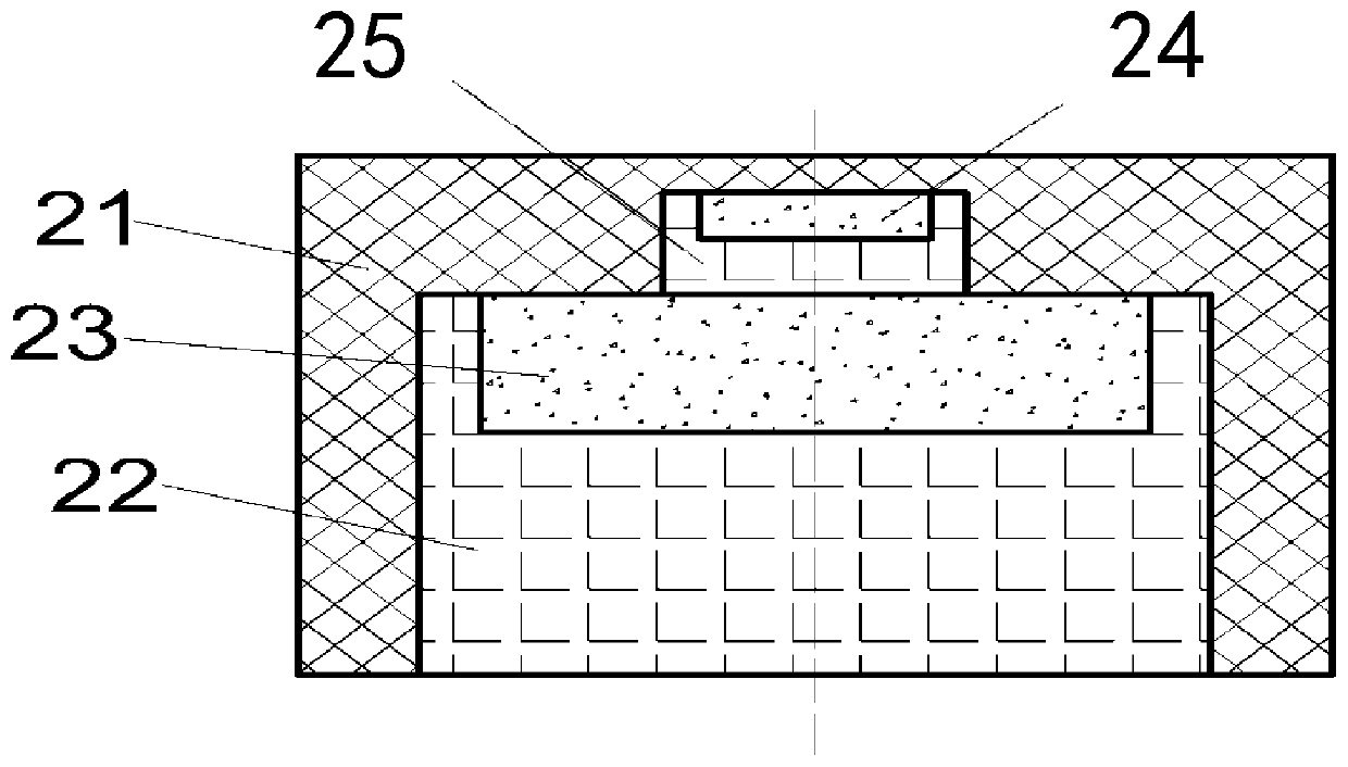
[0028] The present invention proposes a nested structure of piezoelectric discs, the cross-sectional structure of which is as follows figure 2 As shown, the nesting structure of the piezoelectric disc includes a housing 21, a cylindrical first filling body 22 is installed at the bottom of the housing 21; a first functional body 23 is installed on the top of the first filling body 22; In the middle of the upper surface of the first functional body 23, an upwardly protruding second filler body 25 is arranged, and a second functional body 24 is arranged on the top of the second filler body 25; in this nested structure, the first functional body 23 A piezoelectric disc with a lower frequency is used; the second functional body 25 adopts a piezoelectric sheet for high-frequency transmission and reception, and the piezoelectric disc and the piezoelectric sheet are both cylindrical structures; and the thickness of the piezoelectric disc is greater than that of the piezoelectric sheet...

Embodiment 2

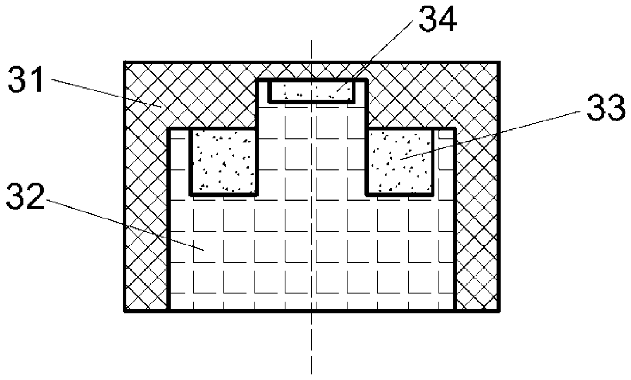
[0030] On the basis of Embodiment 1, the present invention proposes a nested structure of piezoelectric rings, the cross-sectional structure of which is as follows image 3 As shown, the nested structure of the piezoelectric ring includes a housing 31, and a convex first filling body 32 is installed at the bottom of the housing 31; A functional body 33; a second functional body 34 is arranged on the upper top of the first filling body 32; in this nested structure, the ring-shaped first functional body 32 adopts a lower frequency piezoelectric ring; the second functional body adopts Piezoelectric sheets for high-frequency transmission and reception; just because the first functional body 32 adopts a piezoelectric ring structure, the first functional body 33 does not directly contact the second filling body. The second filling body 24 is merged with the first filling body 23 to form a convex first filling body 32 in this embodiment; similarly, the thickness of the piezoelectric ...

Embodiment 3

[0032] On the basis of Embodiment 2, the present invention proposes a nested structure of concave cover plates, the cross-sectional structure of which is as follows Figure 4 As shown, the ring-shaped nesting structure includes a downwardly concave shell 41, that is, the cover plate of the shell 41 is a concave cover plate, and a convex first filling body is installed on the bottom of the shell 41. 42; An annular first functional body 43 is installed on the top of both shoulders of the first filling body 42; a second functional body 44 is arranged on the upper top of the first filling body 42; this embodiment adopts a concave cover plate to make the beam Focusing can obtain a narrower beam than the structure of embodiment 2, so that the acoustic energy is more focused and the detection distance is longer.


PUM


Abstract

The invention belongs to an electricity and sound energy conversion structure, and particularly belongs to an ultrasonic transducer and a nested structure thereof. The nested structure comprises a first filling body mounted at the bottom of a shell; a first functional body is mounted at the top of the first filling body; a second filling body protruding upwards is arranged in the middle of the upper surface of the first functional body, and a second functional body is arranged at the top of the second filling body; and the first functional body is made of a low-frequency ultrasonic emission material, and the second functional body is made of a high-frequency ultrasonic emission material, wherein the sectional area of the second functional body is smaller than that of the second filling body; and the sectional area of the first functional body is smaller than that of the first filling body. The thickness of the first filling body in the central circular area of the nested structure is small, and the thickness of the second filling body in the peripheral circular area is large; and the first filling body uses a high-frequency transceiving piezoelectric sheet as an excitation element,and the second filling body uses a low-frequency piezoelectric wafer or piezoelectric ring as an excitation element, so that double-frequency-point work is realized.

Description

technical field [0001] The invention belongs to an electric-acoustic energy conversion structure, in particular to an ultrasonic transducer and its nested structure. Background technique [0002] Ultrasonic liquid level gauge is the fastest growing instrument in non-contact measurement. It is based on the principle that ultrasonic waves are reflected on the surface of the object to be measured, and the functional relationship between the measured distance and time to achieve distance measurement. Ultrasonic liquid level gauge has the advantages of wide measurement range and no influence of medium density and dielectric constant. It is suitable for various measurement media such as gas, liquid or solid, and has a wide range of applications, including water channels, oil tanks, gas tanks, etc. It can also be used in liquid level measurement of viscous, corrosive and toxic liquids. [0003] The Chinese patent "An Improved Vibrator Structure for Ultrasonic Liquid Level Gauge" ...

Claims


Application Information

Patent Timeline
Patent Type & Authority Applications(China)
IPC IPC(8): G01F23/296B06B1/06
CPCG01F23/2968B06B1/06B06B2201/55
Inventor 王登攀杨靖张毅张祖伟袁宇鹏李小飞梅勇
Owner CETC CHIPS TECH GRP CO LTD
Learn More