Hybrid energy supply sudden short circuit test device and test method

A short-circuit test and energy supply technology, applied in measurement devices, circuit devices, measurement power and other directions, can solve the problems of adverse effects of power supply quality of power grid, reduction of volume and manufacturing cost, and high requirements for energy storage scale, and achieve comprehensive testing ability improvement, Expand the test output parameters and the effect of strong device adaptability

Pending Publication Date: 2020-07-31
XI AN JIAOTONG UNIV
View PDF6 Cites 1 Cited by
  • Summary
  • Abstract
  • Description
  • Claims
  • Application Information

AI Technical Summary

Problems solved by technology

The first one is to output to both ends of each output sub-module after isolation and rectification of the alternating current of the power grid. Although this method realizes the flexible control of the output and the adjustment of the power factor, it is highly dependent on the power grid, and the access of the switching device will be difficult. Cause large harmonics, which will have a negative impact on the quality of power grid power supply
The second adopts the scheme of "charging the energy storage units in parallel first, then disconnecting them, and finally discharging them in series". This method reduces the use of isolation transformers, greatly reduces the volume and manufacturing cost, but also has short discharge duration. , high energy storage scale requirements and other issues

Method used


Image

  • Hybrid energy supply sudden short circuit test device and test method
  • Hybrid energy supply sudden short circuit test device and test method
  • Hybrid energy supply sudden short circuit test device and test method

Examples


Embodiment Construction

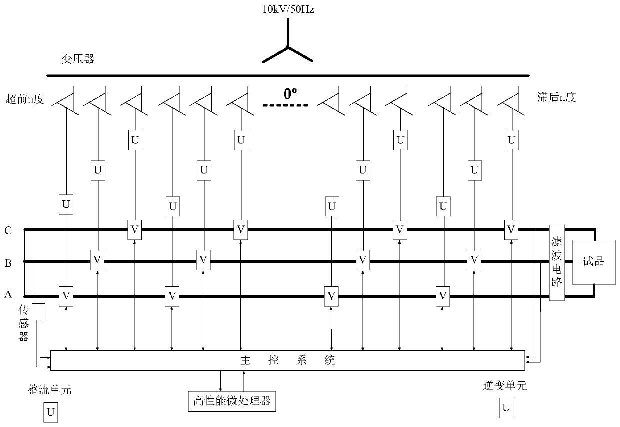
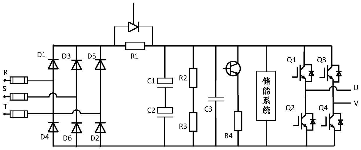
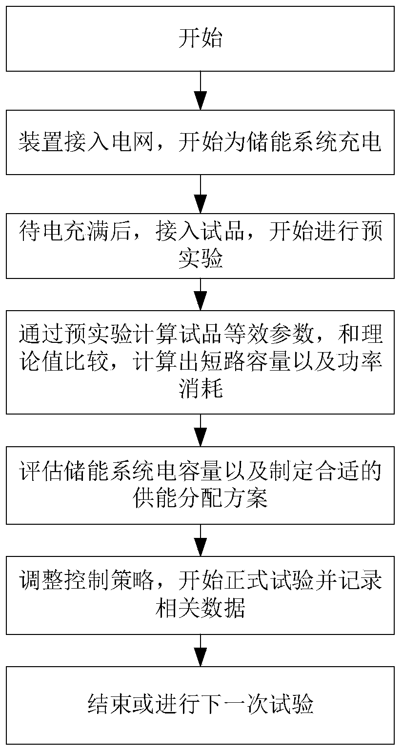
[0036] The following will refer to the attached figure 1 To attach image 3 Specific examples of the present invention are described in more detail. Although specific embodiments of the invention are shown in the drawings, it should be understood that the invention may be embodied in various forms and is not limited to the embodiments set forth herein. Rather, these embodiments are provided for more thorough understanding of the present invention and to fully convey the scope of the present invention to those skilled in the art.

[0037] It should be noted that certain terms are used in the specification and claims to refer to specific components. Those skilled in the art should understand that they may use different terms to refer to the same component. The specification and claims do not use differences in nouns as a way of distinguishing components, but use differences in functions of components as a criterion for distinguishing. "Includes" or "comprises" mentioned thro...


PUM


Abstract

The invention discloses a hybrid energy supply sudden short circuit test device and method. The device comprises a power grid output side, a multi-stage phase-shifting transformer, a rectifying unit,an inversion unit, a filtering unit, a control system and a measurement loop of the control system connected in sequence. The multi-stage phase-shifting transformer is connected with the output side of the power grid to generate alternating-current three-phase power with different preset phase-shifting angles. The rectifying unit rectifies the alternating-current three-phase power to generate direct current. A rectification power supply is connected with the DC side of the inversion unit. The energy storage unit is configured to be connected with the rectification unit to store DC. And a direct current side connected with the inversion unit to provide direct current, the inversion unit generates a voltage and a current of a predetermined waveform based on the direct current. The filteringunit is connected with the inversion unit to filter voltage and current, the control system is connected with the multistage phase-shifting transformer and the energy storage unit to control energy supply distribution, the control system is connected with the rectification unit, the inversion unit and the filtering unit to generate expected voltage and current, and the measurement loop is connected with a to-be-tested product to measure electrical parameters based on the expected voltage and current.

Description

technical field [0001] The invention belongs to the technical field of high-voltage and high-power testing, in particular to a hybrid energy supply sudden short-circuit testing device and testing method. Background technique [0002] With the improvement of the power grid's detection requirements for the transformer's anti-sudden short-circuit capability, the traditional burst-short-circuit test source is becoming more and more inapplicable due to problems such as high manufacturing and testing costs and inflexible control. With the development of semiconductor devices and energy storage technologies, power electronic short-circuit test devices have attracted extensive attention due to their small footprint and flexible control. There are mainly two energy supply methods for current power electronic short-circuit test devices. The first one is to output to both ends of each output sub-module after isolation and rectification of the alternating current of the power grid. Alt...

Claims


Application Information

Patent Timeline
Patent Type & Authority Applications(China)
IPC IPC(8): G01R31/00H02J3/00H02J3/28
CPCG01R31/00H02J3/00H02J3/28Y02E40/10
Inventor 梁成军刘轩东
Owner XI AN JIAOTONG UNIV
Why Eureka
Try Eureka