Optical module

An optical module and laser technology, which is applied in the field of optical communication, can solve the problems that the heat of laser emitting components and silicon photonic chips cannot be dissipated in time, which affects the performance of optical modules, etc.

Inactive Publication Date: 2020-07-31
HISENSE BROADBAND MULTIMEDIA TECH
View PDF5 Cites 6 Cited by
  • Summary
  • Abstract
  • Description
  • Claims
  • Application Information

AI Technical Summary

Problems solved by technology

[0004] However, since the laser emitting component and the silicon photonic chip are arranged on the surface of the circuit board, the heat generated

Method used


Image

  • Optical module
  • Optical module
  • Optical module

Examples


Example Embodiment

[0040] The technical solutions in the embodiments of the present invention will be clearly and completely described below in conjunction with the accompanying drawings in the embodiments of the present invention. Obviously, the described embodiments are only a part of the embodiments of the present invention, rather than all the embodiments. Based on the embodiments of the present invention, all other embodiments obtained by those of ordinary skill in the art without creative work shall fall within the protection scope of the present invention.

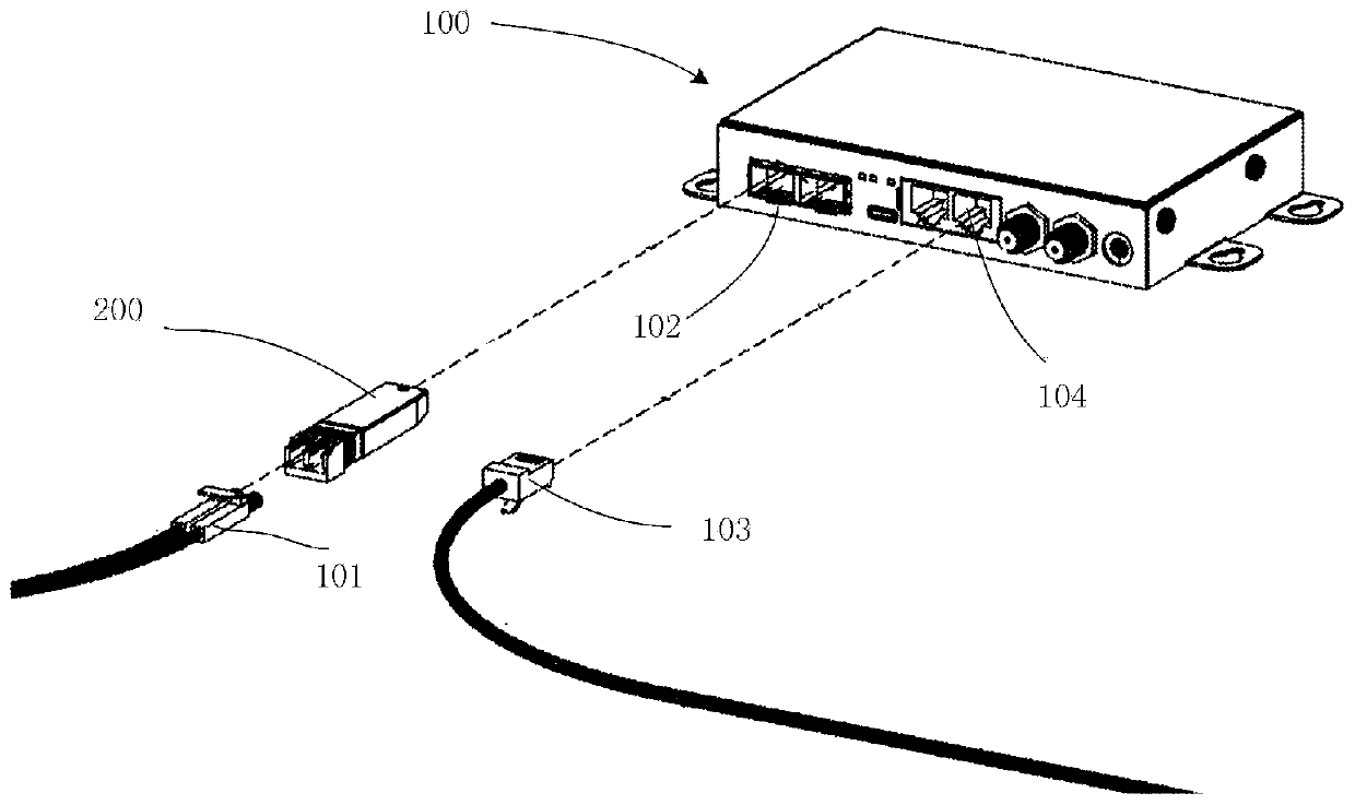
[0041] One of the core links of optical fiber communication is the mutual conversion of optical and electrical signals. Optical fiber communication uses information-carrying optical signals to be transmitted in optical fibers / optical waveguides and other information transmission equipment, and the passive transmission characteristics of light in optical fibers / optical waveguides can achieve low-cost and low-loss information transmission; ...


PUM


Abstract

The invention provides an optical module. The optical module comprises a lower shell and a circuit board attached to the lower shell, wherein an empty groove is formed in the circuit board, and a laser assembly and a silicon optical chip which are attached to the lower shell are arranged in the empty groove; a laser assembly which is in routing connection with the circuit board and is used for emitting light without carrying signals; and a silicon optical chip which is in routing connection with the circuit board and is used for modulating the light which does not carry the signal. In the present application, the empty groove is formed in the circuit board, the laser assembly and the silicon optical chip are arranged in the empty groove, and the circuit board, the laser assembly and the silicon optical chip are all directly fixed on the lower shell so that barriers among the laser assembly, the silicon optical chip and the lower shell are reduced, heat generated by the laser assembly and the silicon optical chip is conveniently dissipated in time, and the working performance of the optical module is not influenced.

Description

technical field [0001] The present application relates to the technical field of optical communication, and in particular to an optical module. Background technique [0002] In optical communication, optical module is one of the key components in optical communication equipment. With the development of optical communication, the integration of optical modules is getting higher and higher, and the power density of optical modules is also increasing, resulting in a large amount of heat generated inside the optical modules during operation. And if the heat generated inside the optical module cannot be dissipated in time, it will seriously affect the performance of the optical module. [0003] In the traditional optical module, the laser emitting component and the silicon photonic chip are arranged on the surface of the circuit board, and the silicon photonic chip and the circuit board are electrically connected by wire bonding; light chip. [0004] However, since the laser e...

Claims


Application Information

Patent Timeline
IPC IPC(8): G02B6/42
CPCG02B6/4256G02B6/4268G02B6/428
Inventor 郑龙杨思更
Owner HISENSE BROADBAND MULTIMEDIA TECH
Why Eureka
Try Eureka