Charging energy storage system and charging pile equipment

An energy storage system and charging pile technology, applied in charging stations, charging/discharging current/voltage regulation, vehicle energy storage, etc., can solve problems such as high cost of reconstruction and re-connection to the grid, difficult maintenance, large grid load, etc., to achieve The effect of reducing equipment maintenance costs, shortening construction time, and reducing transformation costs

Inactive Publication Date: 2020-07-31
西安新衡科测控技术有限责任公司
View PDF19 Cites 1 Cited by
  • Summary
  • Abstract
  • Description
  • Claims
  • Application Information

AI Technical Summary

Problems solved by technology

[0003] First, the power of the charging equipment equipped for vehicles is relatively large, and power must be taken from the mains power grid. The commonly used technical method is that the mains power is directly charged to vehicles after being converted by the AC / DC module or DC / DC module output of the charging equipment. This will lead to a large load on the power grid when there are many users charging vehicles at the same time, which will cause an impact on the power grid in the entire region
[0004] Second, the current number of electric vehicles is increasing rapidly. When the charging piles cannot meet the needs of residents, the cost of rebuilding and re-connecting to the network is very high, which makes it difficult to rebuild charging points, thus causing a certain contradiction between supply and demand.
[0005] Third, when a battery cell in the charging device is damaged, the entire charging device cannot be used, and maintenance is difficult, affecting use

Method used


Image

  • Charging energy storage system and charging pile equipment
  • Charging energy storage system and charging pile equipment
  • Charging energy storage system and charging pile equipment

Examples


Embodiment 1

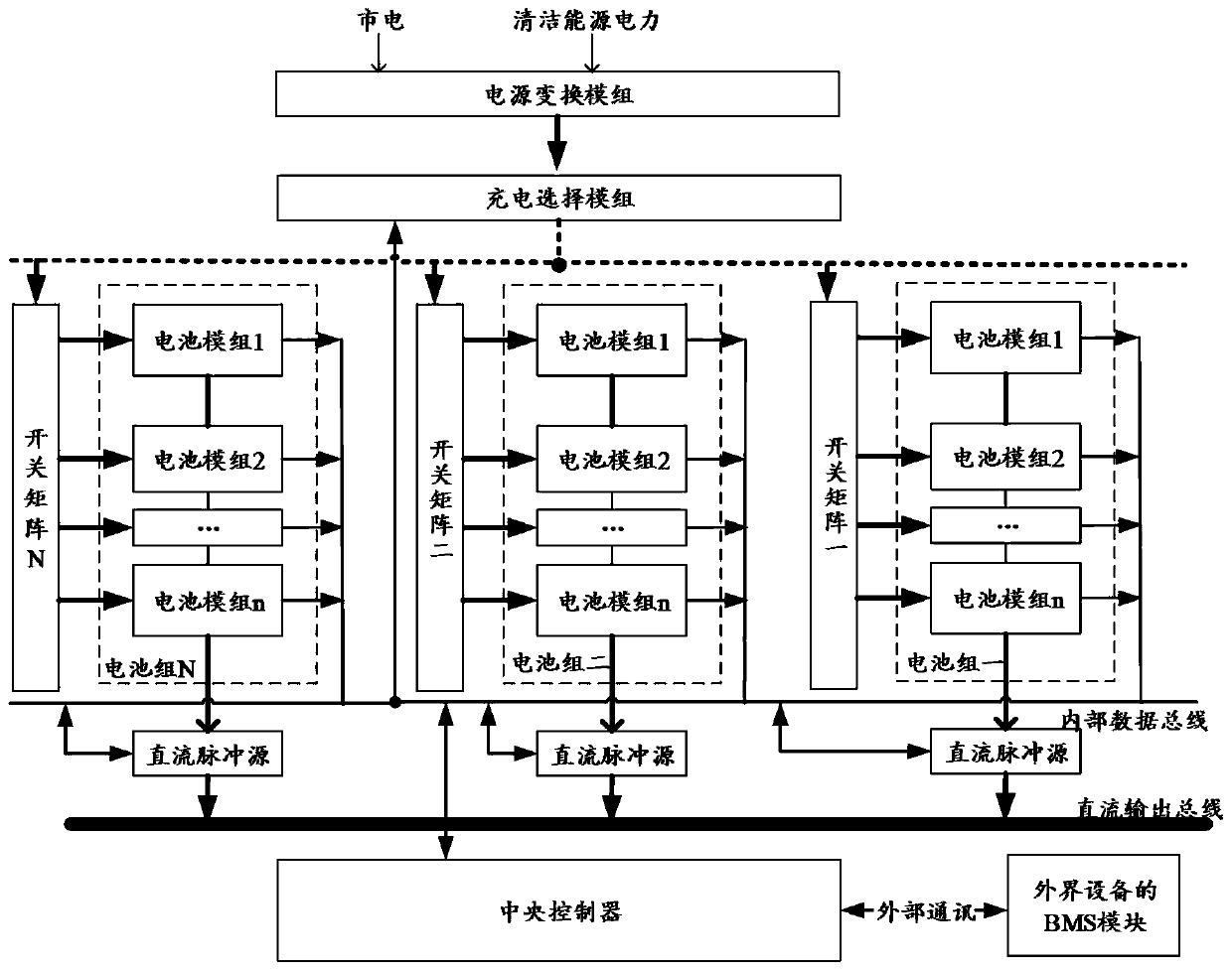
[0045] see figure 1 As shown, Embodiment 1 of the present invention provides a charging energy storage system, including: a power conversion module, a charging selection module, a central controller, a battery pack, a switch matrix and a DC pulse source;

[0046] Wherein, the number of battery packs is greater than 1; each battery pack contains at least one battery module, and the battery module has a detachable structure;

[0047] The number of switch matrices is the same as the number of battery packs and has a unique corresponding relationship, which is used to turn on the charging circuit of the battery module to be charged after receiving the charging instruction from the charging selection module;

[0048] The number of DC pulse sources is the same as the number of battery packs and has a unique correspondence, which is used to adjust the output current of the corresponding battery pack based on the expected value of the output current of the system; the outputs of all D...

Embodiment 2

[0073] Based on the foregoing embodiment 1, Embodiment 2 of the present invention provides a charging pile device, which not only has the advantages of the foregoing Embodiment 1, but also can join the Internet of Things for data sharing.

[0074] Such as Figure 4 As shown, in addition to the charging energy storage system in the aforementioned embodiment 1, the structure of the charging pile equipment also includes an Internet of Things communication system, which is used to establish a communication connection with the central controller of the charging energy storage system. And send the communication information of the charging energy storage system to other devices in the same Internet of Things.

[0075] Specifically, the communication information of the charging energy storage system here includes but is not limited to: charging indication, expected output current value of the system, SOC value and charging voltage of each battery module, battery module to be charged, ...


PUM


Abstract

The invention, which relates to the technical field of battery energy storage, discloses a charging energy storage system comprising a power conversion module, a charging selection module, a central controller, battery packs, a switch matrix and a direct-current pulse source. The number of battery packs is greater than 1; each battery pack comprises at least one battery module, and each battery module is provided with a detachable structure; the switch matrix is used for conducting a charging loop of each battery module to be charged; the direct-current pulse source is used for adjusting the output current of the corresponding battery pack; the power conversion module is used for modulating the charging voltage of the battery module to be charged; the central controller is used for acquiring an output current expected value of the system, an SOC value of each battery module and a charging voltage; the charging selection module is used for determining a to-be-charged battery module. Theinvention further discloses charging pile equipment related to the charging energy storage system. The load impact of the system on a power grid is reduced while an energy storage battery cell is effectively protected, the battery cell is convenient to expand and replace, and the cost is saved.

Description

technical field [0001] The invention relates to the technical field of battery energy storage, in particular to a charging energy storage system and charging pile equipment. Background technique [0002] With the popularization of electric vehicles and the social demand for environmental protection, the demand for the construction of various high-power charging equipment (such as charging piles) is getting higher and higher, and there are also new problems that follow, as follows: [0003] First, the power of the charging equipment equipped for vehicles is relatively large, and power must be taken from the mains power grid. The commonly used technical method is to directly charge the vehicles after the mains power is transformed by the AC / DC module or DC / DC module output of the charging equipment. This will lead to a large load on the power grid when there are many users charging vehicles at the same time, which will cause an impact on the power grid in the entire region. ...

Claims


Application Information

Patent Timeline
Patent Type & Authority Applications(China)
IPC IPC(8): H02J7/00H02J3/32B60L53/53
CPCB60L53/53H02J3/32H02J7/007Y02T10/70Y02T10/7072Y02T90/12
Inventor 荆涛
Owner 西安新衡科测控技术有限责任公司
Why Eureka
Try Eureka