Combustion controlling circuit

A technology for controlling circuits and circuits, which can be used in the control of combustion, heating fuel, gaseous heating fuel, etc., and can solve the problems of large-scale machines and increased costs.

Inactive Publication Date: 2003-07-16
RINNAI CORP
View PDF0 Cites 0 Cited by
  • Summary
  • Abstract
  • Description
  • Claims
  • Application Information

AI Technical Summary

Problems solved by technology

At this time, when the load current used to make the above-mentioned circuits is relatively large, in order to adapt to the large load current during ignition operation, components such as transformers or silicon bridges that constitute the power supply circuit must use large components with high ratings, which will lead to Increase in machine size and cost

Method used


Image

  • Combustion controlling circuit
  • Combustion controlling circuit
  • Combustion controlling circuit

Examples


Embodiment

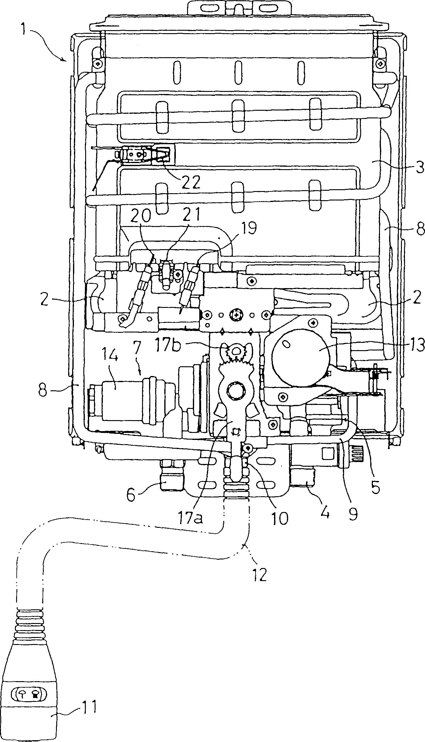
[0021] Next, an example of applying the combustion control circuit of the present invention to figure 1 An embodiment of the water heater 1 is shown.

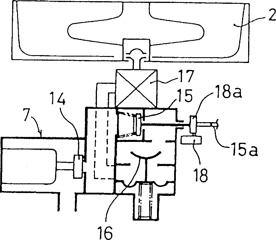
[0022] The water heater 1 has a gas burner 2 and a heat exchanger 3 using the gas burner 2 as a heat source. Also have the water valve assembly 5 that is arranged on the lower end of water heater 1 and be connected with the water pipe joint 4 on the running water pipe (not shown in the figure) and be arranged on the lower end of water heater 1 and be connected with the gas pipe (not shown in the figure) The gas valve assembly 7 that the gas pipe on the outlet) is connected with the joint 6.

[0023] The heat exchange channel 8 passing through the heat exchanger 3 and the bypass channel 9 not passing through the heat exchanger 3 are connected to the downstream side of the water valve assembly 5 . The downstream end of the heat exchange channel 8 and the downstream end of the bypass channel 9 are connected to a mixing unit 10 ...


PUM


Abstract

To decrease a maximum load current in a combustion control circuit using as a power source a power source circuit for converting an alternating current from a battery or a commercial power source into a direct current. A combustion control circuit comprises a valve opening circuit 23 for forcedly opening a safety valve 14 under an electromagnetic force, a holding circuit 24 for opening and holding the safety valve 14, an ignition circuit 25 and a flame rod circuit 26. During an ignition operation, the valve opening circuit 23 is operated for a short time, and the holding circuit 24 and the ignition circuit 25 are operated for a prescribed ignition time. Then, after the operation of the valve opening circuit 23 is completed, the flame rod circuit 26 is operated.

Description

technical field [0001] The present invention relates to a combustion control circuit suitable for burners such as water heaters. More specifically, it relates to a combustion control circuit powered by a battery or a power circuit that converts alternating current from commercial power into direct current. Background technique [0002] In the burner, as a measure to prevent the release of gas in case of fire, an electromagnetic safety valve is installed on the fuel supply pipeline of the burner. . To operate the burner, the electromagnetic safety valve is opened during the ignition operation, and then, while the ignition of the burner is detected by a thermocouple or a flame rod, the electromagnetic safety valve is kept open to continue operation. In addition, when the thermocouple or flame rod detects that the burner is on fire, the electromagnetic safety valve is closed to prevent the release of gas. [0003] Here, as a method of opening the electromagnetic safety valve,...

Claims


Application Information

Patent Timeline
IPC IPC(8): F23N5/24F23N5/00F23N5/20F24C3/12F24H9/20
CPCF23N5/203F23N5/24
Inventor 安藤厚史栗木圭一
Owner RINNAI CORP
Why Eureka
Try Eureka