
Plant transfer printing equipment and application method thereof

A technology for printing and dyeing equipment and plants, applied in the field of plant printing and dyeing equipment, can solve problems such as low work efficiency, different organizational structures, and different shapes, and achieve the effect of improving flatness

Inactive Publication Date: 2020-08-04
绍兴柯桥富荣纺织有限公司
View PDF0 Cites 5 Cited by
  • Summary
  • Abstract
  • Description
  • Claims
  • Application Information

AI Technical Summary

Problems solved by technology

[0004] The purpose of the present invention is to solve the problem that plant roots, stems, leaves and other parts have different tissue structures and shapes during manual beating, and it is difficult to uniformly print and dye the pigments in plants on the surface of paper or fabrics through simple manual beating, so manual beating It is not easy to master the strength, and there is a problem of low work efficiency at the same time, and a plant printing and dyeing equipment and its use method are proposed

Method used


Image

  • Plant transfer printing equipment and application method thereof
  • Plant transfer printing equipment and application method thereof
  • Plant transfer printing equipment and application method thereof

Examples


Embodiment 1

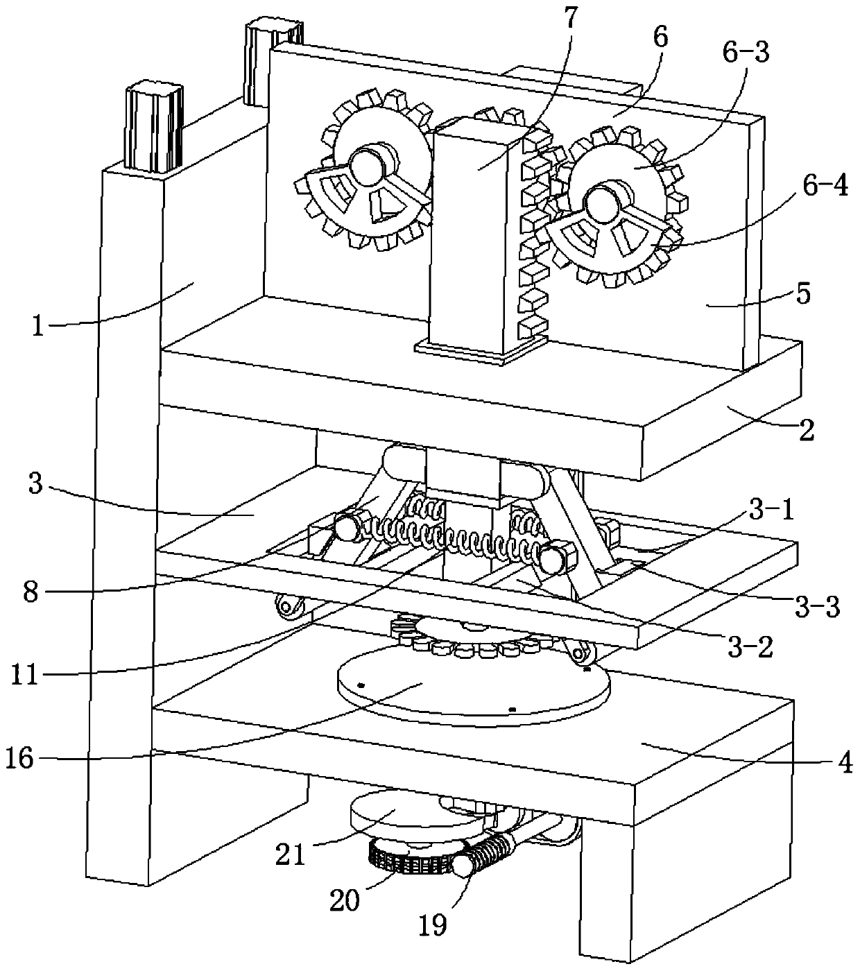
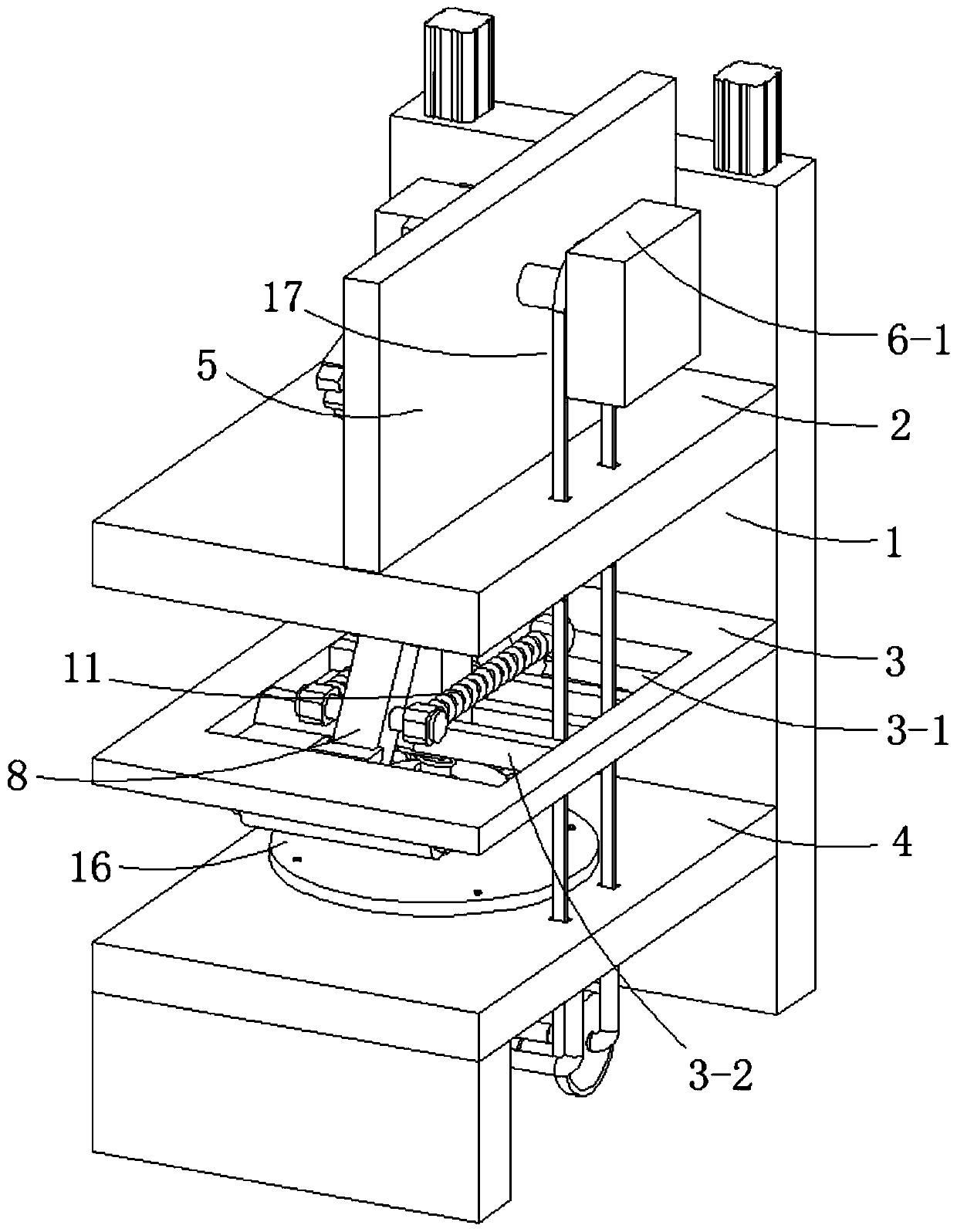
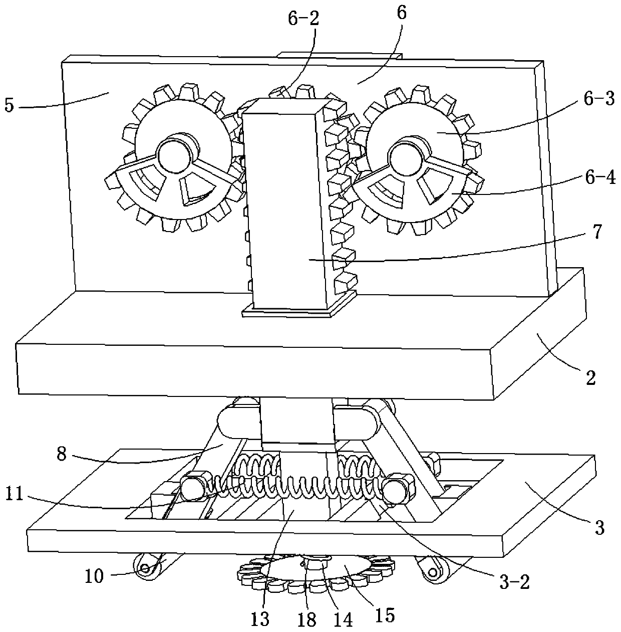
[0037] Embodiment one, with reference to Figure 1-8 , a plant printing and dyeing equipment, comprising a support plate 1, a mounting plate 2, a limiting plate 3, and a workbench 4 are sequentially fixed downward along the vertical direction of the support plate 1; a vertical plate is fixed vertically on the top of the mounting plate 2 5. The side wall of the vertical plate 5 is provided with a reciprocating mechanism 6, and the top of the mounting plate 2 is telescopically connected with a telescopic rack 7, and the output end of the reciprocating mechanism 6 is engaged with the telescopic rack 7, and the outer wall of the bottom end of the telescopic rack 7 A symmetrical transfer rod 8 is rotationally connected, and the bottom end of the transfer rod 8 is fixed with a mounting block 9 through a spring 26. The bottom of the transfer rod 8 is fixed with a fixed column 27, and the mounting block 9 is slidably arranged on the fixed column 27. Above, one end of the spring 26 is ...

Embodiment 2

[0052] Embodiment 2: The setting mode of driving dial 21, sheave 22, driving lever 23, cylindrical pin 24 and radial groove 25 in the intermittent motion mechanism in the present invention is not limited to the mode of the external connection type of the above-mentioned embodiment one, but also can be set as Figure 7 The form shown, that is, adopts the internal connection type, the driving dial 21 is arranged on the inner side of the sheave 22, and the driving dial 21 intermittently moves the sheave 22 through the cylindrical pin 24 on it when rotating, and the groove The wheel 22 further drives the turntable 16 to rotate intermittently, so that the plants are intermittently beaten by the beating disc 15, so that the plant pigments can be evenly printed and dyed on the surface of the plants.


PUM


Abstract

The invention discloses plant transfer printing equipment and an application method thereof and belongs to the technical field of plant transfer printing equipment. The plant transfer printing equipment comprises a supporting plate. A mounting plate, a limiting plate and a worktable are fixedly arranged downward in a vertical direction of the supporting plate successively. A vertical plate is vertically and fixedly arranged on the top of the mounting plate, a reciprocating mechanism is arranged on the side wall of the vertical plate, a telescopic rack is further telescopically connected to thetop of the mounting plate, an output end of the reciprocating mechanism is engaged to the telescopic rack, the outer wall of the bottom end of the telescopic rack is rotatably connected to symmetrical adapting rods, and mounting blocks are fixedly arranged at the bottom ends of the adapting rods through springs. By arranging the reciprocating mechanism to drive a beating disc to stretch to beat plants among fabrics on a turnplate, plant pigments are transfer printed to the fabrics uniformly. In addition, an arranged driving mechanism drives the turnplate to rotate intermittently, so that after the turnplate stops intermittent rotation, the plants are beaten and transfer printed through the beating disc.

Description

technical field [0001] The invention relates to the technical field of plant printing and dyeing equipment, in particular to a plant printing and dyeing equipment and a method for using the same. Background technique [0002] Plant printing and dyeing refers to the method of dyeing the dyed object by using various pigment-containing plant extracts that grow naturally in nature. In the dyeing process, no or very little chemical auxiliaries are used, and the dyes obtained from nature are used. Natural dyes, a process of dyeing products. The charm of plant printing and dyeing is that it makes full use of the roots, stems, leaves, flowers, skins and other parts of fresh plants, extracts their pigments and shapes, and dyes them on fabrics or paper. It is a unique ancient process similar to "printing". The most beautiful moment of the plant can be left on the cloth, so it has cultural significance, environmental protection significance, and aesthetic level significance. [0003]...

Claims


Application Information

Patent Timeline
Patent Type & Authority Applications(China)
IPC IPC(8): D06B5/22D06B23/04D06B23/02D06B23/20
CPCD06B5/22D06B23/02D06B23/04D06B23/20
Inventor 冯小军
Owner 绍兴柯桥富荣纺织有限公司
Learn More