
A heating and rectifying integrated device

A technology of a rectifying plate and a baffle plate, applied in the field of combustion, can solve the problems of large volume and high production cost, and achieve the effects of ensuring safety, reducing volume and cost, and ensuring combustion efficiency and combustion stability.

Active Publication Date: 2022-02-25
INST OF ENGINEERING THERMOPHYSICS - CHINESE ACAD OF SCI
View PDF5 Cites 0 Cited by
  • Summary
  • Abstract
  • Description
  • Claims
  • Application Information

AI Technical Summary

Problems solved by technology

However, the flue gas generating device and the flue gas rectifying device are bulky and costly to manufacture

Method used


Image

  • A heating and rectifying integrated device
  • A heating and rectifying integrated device
  • A heating and rectifying integrated device

Examples


Embodiment Construction

[0054] Hereinafter, embodiments of the present invention will be described with reference to the drawings. It should be understood, however, that these descriptions are exemplary only and are not intended to limit the scope of the present invention. In the following detailed description, for purposes of explanation, numerous specific details are set forth in order to provide a thorough understanding of the embodiments of the invention. It may be evident, however, that one or more embodiments may be practiced without these specific details. Also, in the following description, descriptions of well-known structures and techniques are omitted to avoid unnecessarily obscuring the concept of the present invention.

[0055] The terminology used herein is for the purpose of describing particular embodiments only, and is not intended to be limiting of the invention. The terms "comprising", "comprising", etc. used herein indicate the presence of stated features, steps, operations and / ...


PUM


Abstract

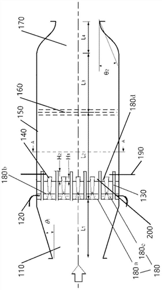
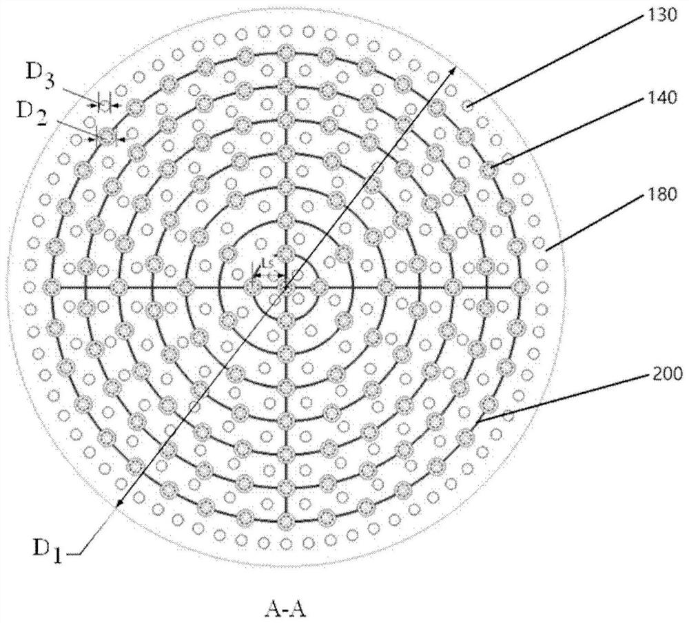
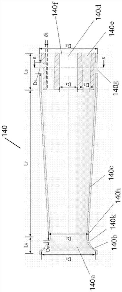
The invention provides a heating and rectifying integrated device, comprising: an air intake conduit, a fuel pipe, an air conduit fixed on a nozzle fixed baffle, a nozzle unit and a cross-flame annular seam, and an ignition device sequentially arranged behind the nozzle fixed baffle Devices, receivers, rectifier plates, exhaust ducts. The integrated heating and rectifying device has a compact structure and can realize efficient and stable flue gas regulation. The nozzle units and air ducts are radially staggered and layered on the nozzle fixed baffle, and evenly distributed along the circumference to ensure the spatial uniformity of the smoke. The high-temperature flue gas mixed with the nozzle unit and the air duct is further uniformed by the rectifying plate, and each nozzle unit is connected by a cross-flame annular seam, which ensures flame propagation and stable combustion.

Description

technical field [0001] The invention relates to the technical field of combustion, in particular to a heating rectification integrated device. Background technique [0002] With the development of the national economy, high-temperature flue gas is widely used as a heat source in the research and development of hot-end components of gas turbines and in oil exploration and refining. In the research and development process of the hot end components of the gas turbine, the flue gas generator is placed upstream of the test section and cooperates with the flue gas rectifier to provide the test section with flue gas under specific flow and temperature conditions, so as to realize the hot end components. A simulation of your real environment. In the field of petrochemical industry, the existing flue gas generator generally adopts a large heating furnace. However, the flue gas generating device and the flue gas rectifying device are bulky and expensive to manufacture. At the same ...

Claims


Application Information

Patent Timeline
Patent Type & Authority Patents(China)
IPC IPC(8): F23D14/00F23D14/46F23D14/58F23D14/70
CPCF23D14/00F23D14/46F23D14/58F23D14/70
Inventor 熊燕刘志刚张哲巅肖云汉
Owner INST OF ENGINEERING THERMOPHYSICS - CHINESE ACAD OF SCI
Learn More