Hidden auxiliary equipment for gas stove for increasing use safety

A technology for auxiliary equipment and gas stoves, applied in lighting and heating equipment, household stoves, heating methods, etc., can solve the problems of pot dumping, pot offset, scalding pots, etc., so as to avoid occupying space and increase the Linkage, the effect of increasing safety

Inactive Publication Date: 2020-08-04
杭州宾戈科技有限公司
View PDF10 Cites 0 Cited by
  • Summary
  • Abstract
  • Description
  • Claims
  • Application Information

AI Technical Summary

Problems solved by technology

[0003] Gas stove is one of the common kitchen utensils. Gas stove refers to kitchen utensils heated by direct fire with liquefied petroleum gas, artificial gas, natural gas and other gas fuels. When in use, the pot is usually placed directly on the hob of the gas stove Above, the mixed gas ejected from the fire hole of the fire distributor is ignited by the ignition device to form a flame, and the food in the pot is heated with the help of these flames. During the cooking process, professional chefs need to constantly shake the spoon to promote the cooking of dishes and seasonings. and make the food evenly heated, but in general households, because it is too difficult to stir the spoon, the food is usually stirred continuously with the help of a shovel. Since the stove frame cannot fix the pot, when the stirring is too strong It will cause the pot to shift, and after a long time, the bottom of the pot will be heated unevenly, which will affect the use effect of the pot, and when taking ingredients or seasonings, turning around or waving your hands may pass through the pot. The handle pushes the pan to move, causing the pan to fall, and the hot food in the pan falls down, causing people to be scalded or injured by the pan, which poses a huge safety hazard

Method used


Image

  • Hidden auxiliary equipment for gas stove for increasing use safety
  • Hidden auxiliary equipment for gas stove for increasing use safety
  • Hidden auxiliary equipment for gas stove for increasing use safety

Examples


Embodiment Construction

[0022] The following will clearly and completely describe the technical solutions in the embodiments of the present invention with reference to the accompanying drawings in the embodiments of the present invention. Obviously, the described embodiments are only some, not all, embodiments of the present invention. Based on the embodiments of the present invention, all other embodiments obtained by persons of ordinary skill in the art without making creative efforts belong to the protection scope of the present invention.

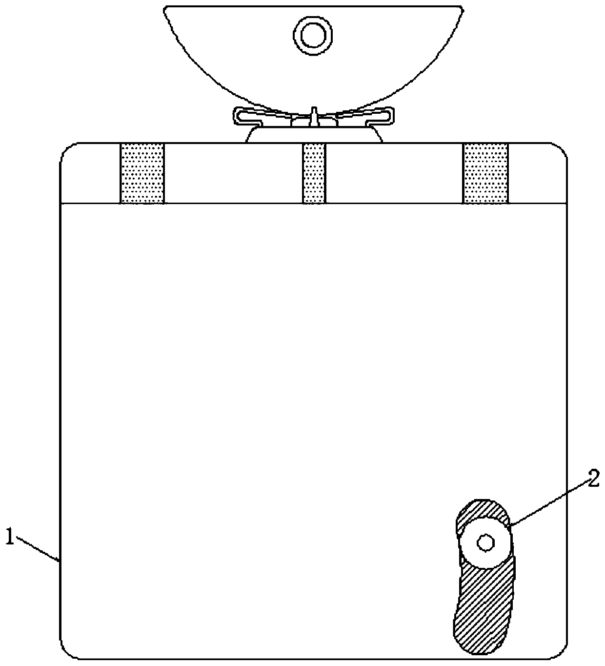
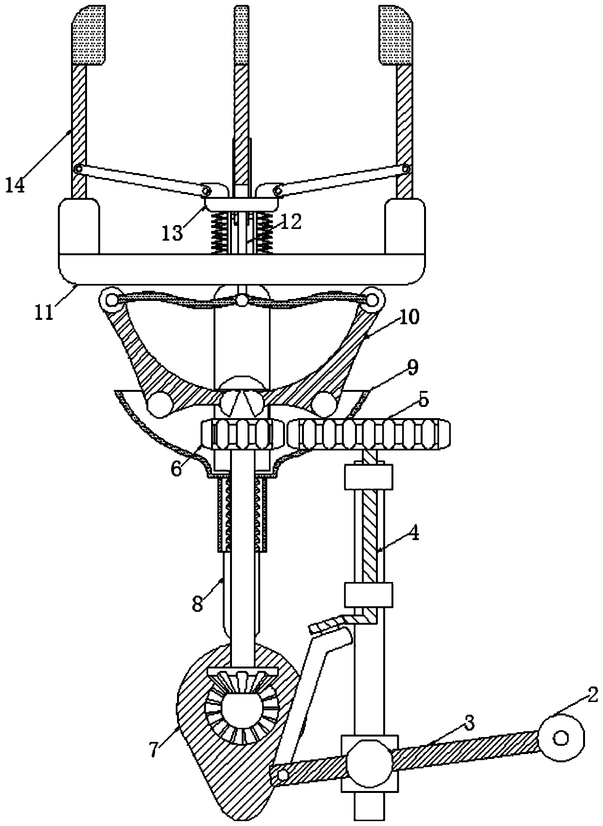
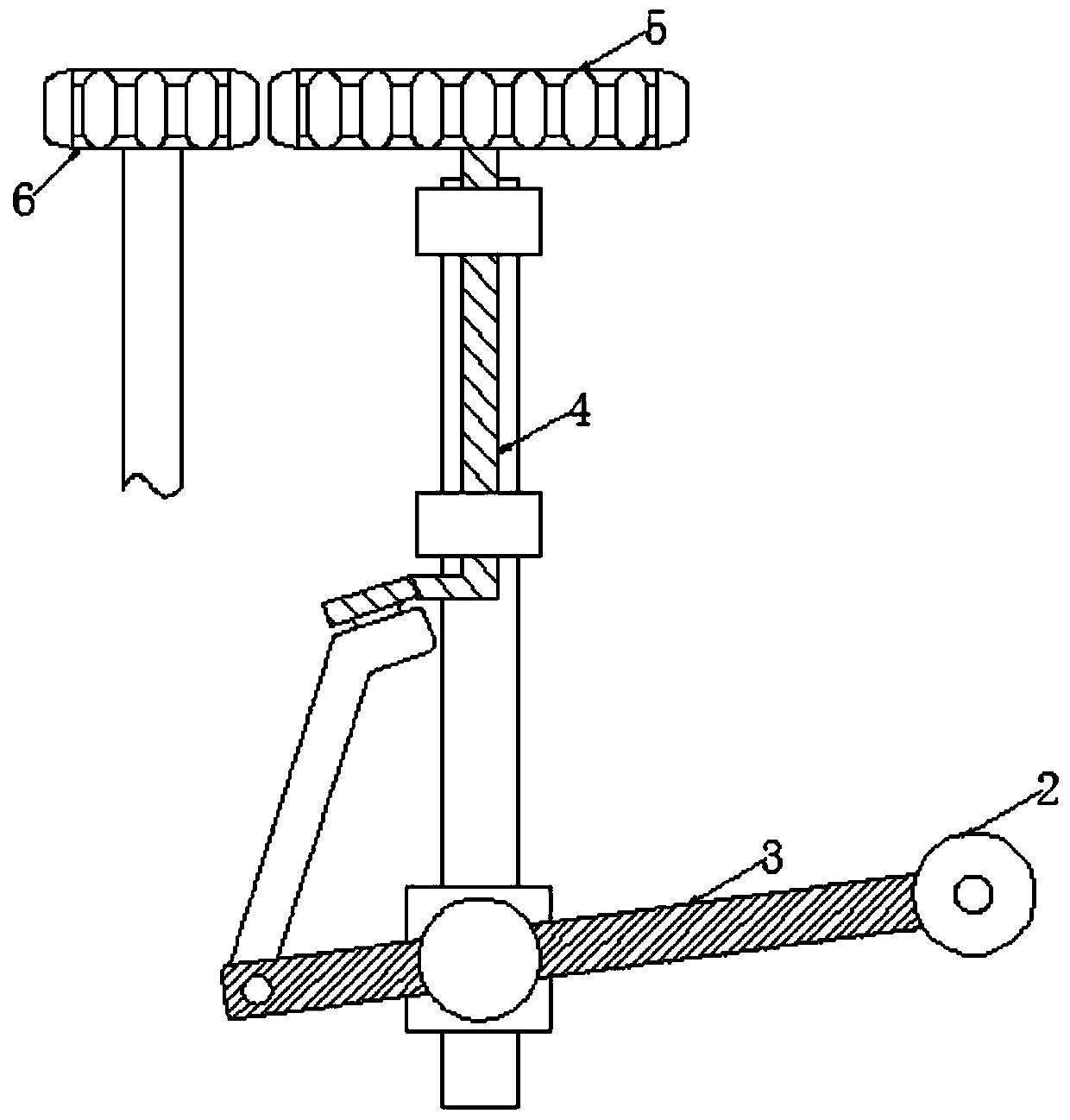
[0023] see Figure 1-5 , a hidden auxiliary device for a gas stove that increases the safety of use, including a casing 1, the top of the casing 1 is fixedly connected to the gas stove, the bottom of the gas stove is fixedly connected to a support plate, and the interior of the support plate is provided with three identically sized Through holes, the size of which matches the size of the clamping rod 14 blocks, the three through holes are equidistantly distrib...


PUM


Abstract

The invention relates to the technical field of household articles, and discloses hidden auxiliary equipment for a gas stove for improving use safety. The hidden auxiliary equipment comprises a shell,and an outer side of the shell is movably connected with a stepping block; the stepping block is treaded downwards to enable a protruding disc to rotate, a power source is provided for subsequent fixing operation, linkage between structures is improved, so that the operation is more convenient; rotation of the protruding disc enables an ejector rod to move upwards to enable a clamping rod at thetop of the base to move upwards, and when needing to be used, a fixing mechanism automatically wraps the outer side of a pot, so that the fixing operation is facilitated; under the non-use condition,the fixing mechanism is hidden, space occupation is avoided, the ejector rod moves upwards to enable a third rotating rod to rotate and drive a pull rod to move downwards, clamping rods get close to each other, clamping blocks of the clamping rods are clamped to the edge of the pot to automatically fix the pot, so that the pot is evenly heated, and the situation that the pot topples over, crushesor scalds people can be avoided; and the safety of use of the gas stoves is increased.

Description

technical field [0001] The invention relates to the daily technical field of household articles, in particular to a hidden auxiliary device for a gas stove with increased safety in use. Background technique [0002] Household items generally refer to furniture, bedding, kitchen and bathroom utensils, interior accessories and commodities needed for daily life, collectively referred to as household items. Among them, kitchen utensils refer to pots and pans, stoves, range hoods, small appliances, etc.; the kitchen is an important part of a family. With the improvement of living standards, people are constantly pursuing the quality of life in the kitchen, especially some fashion Women have higher requirements for modern kitchens. [0003] Gas stove is one of the common kitchen utensils. Gas stove refers to kitchen utensils heated by direct fire with liquefied petroleum gas, artificial gas, natural gas and other gas fuels. When in use, the pot is usually placed directly on the h...

Claims


Application Information

Patent Timeline
Patent Type & Authority Applications(China)
IPC IPC(8): F24C15/10
CPCF24C15/107
Inventor 雷林泉
Owner 杭州宾戈科技有限公司
Why Eureka
Try Eureka