
Detection device and method for accurate butt joint of ship chamber and lock head of ship lift
A detection device and ship lift technology, which is applied to measuring devices, ship lifting devices, and electrical devices, etc., can solve problems such as poor adaptability, broken strands of wire ropes, and damage to servo motors, so as to improve safety, reliability, and accuracy. The effect of smooth docking and reducing failure rate
- Summary
- Abstract
- Description
- Claims
- Application Information
AI Technical Summary
Problems solved by technology
Method used
Image


Examples
Embodiment Construction
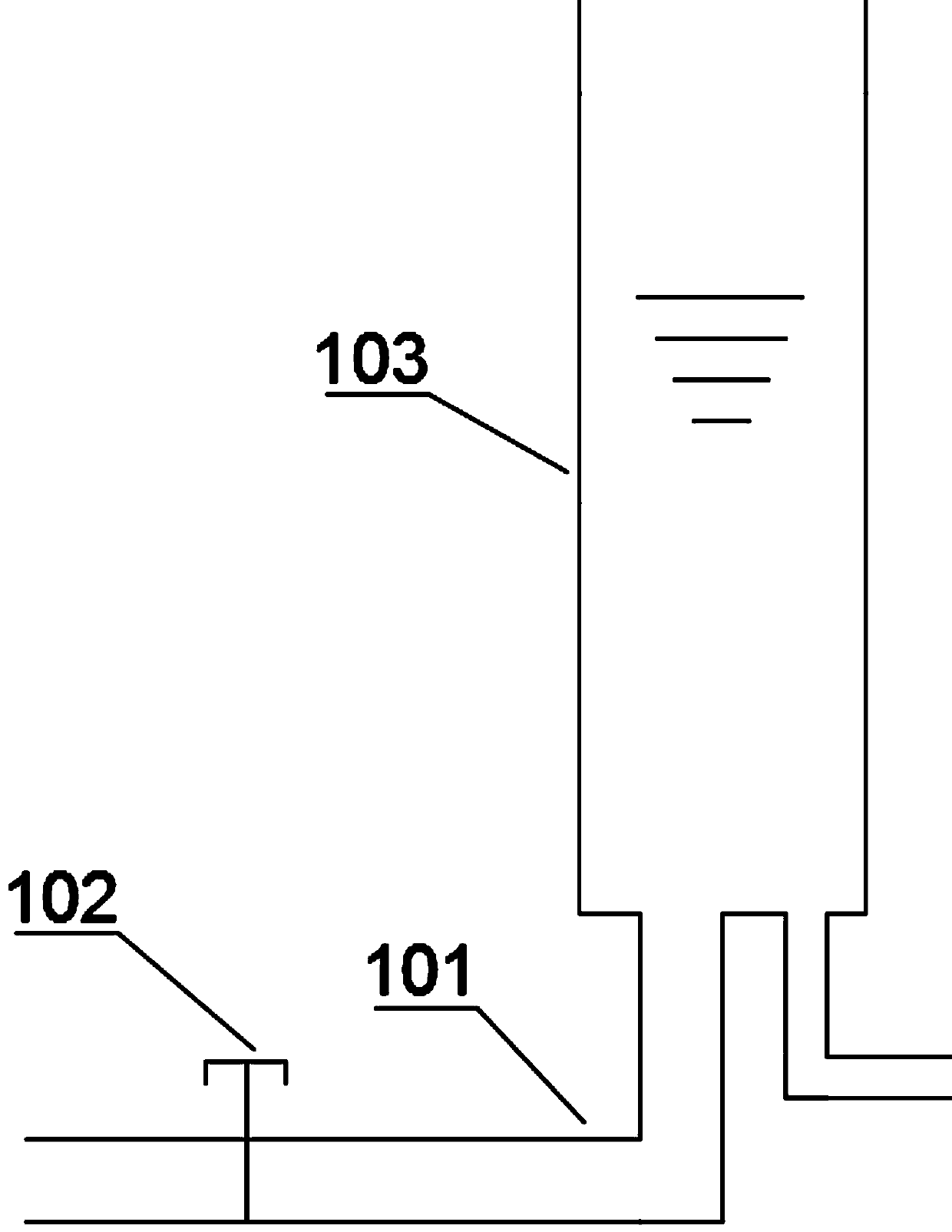
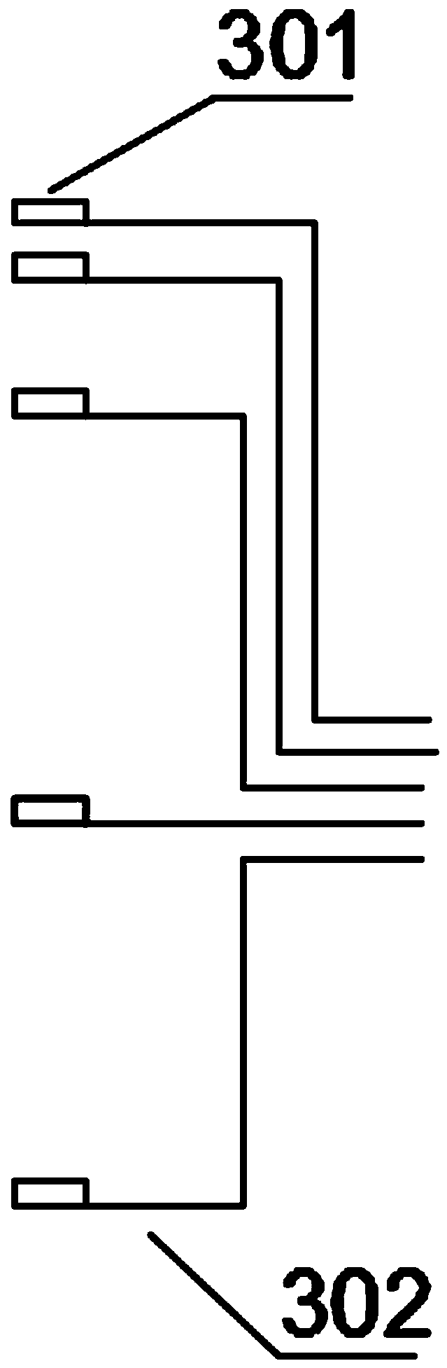
[0027] Such as Figure 1 to Figure 6 As shown, a detection device for the accurate docking of the ship lift cabin and the lock head, including a channel diversion filter unit 1, a channel water depth reflection unit 2, a cabin position detection unit 3, a signal transmission unit 4, and a signal processing unit 5 .
[0028] The channel water diversion filter unit 1 includes a water diversion pipeline 101 and a water storage cylinder 103 , the water diversion pipeline 101 is connected to the water storage cylinder 103 , and a manual valve 102 is provided on the water diversion pipeline 101 .
[0029] This mechanism uses the manual valve 102 as a damping hole, and utilizes the damping effect to reduce the fluctuation of the channel water level change in the water storage cylinder 103 . The principle is as follows: According to the classic pipeline velocity calculation formula: It can be seen that the greater the difference between the water level in the water holding cylinder...
PUM
 Abstract
Description
Claims
Application Information