Offshore scanning type laser radar wind measuring device and method

A technology of laser radar wind measurement and laser radar, which is applied in the direction of measuring device, fluid velocity measurement, radio wave measurement system, etc., can solve the problems of inability to measure tower incoming wind conditions, small working space, etc., and achieve good economic benefits and Application prospect, increase power generation, easy to achieve effect

Pending Publication Date: 2020-08-04
HUANENG GUANYUN CLEAN ENERGY CO LTD +3
View PDF0 Cites 2 Cited by
  • Summary
  • Abstract
  • Description
  • Claims
  • Application Information

AI Technical Summary

Problems solved by technology

However, lidar often needs to be placed on the work platform, which occupies a small work space, and because the radar is fixedly pl

Method used


Image

  • Offshore scanning type laser radar wind measuring device and method
  • Offshore scanning type laser radar wind measuring device and method
  • Offshore scanning type laser radar wind measuring device and method

Examples


Embodiment 1

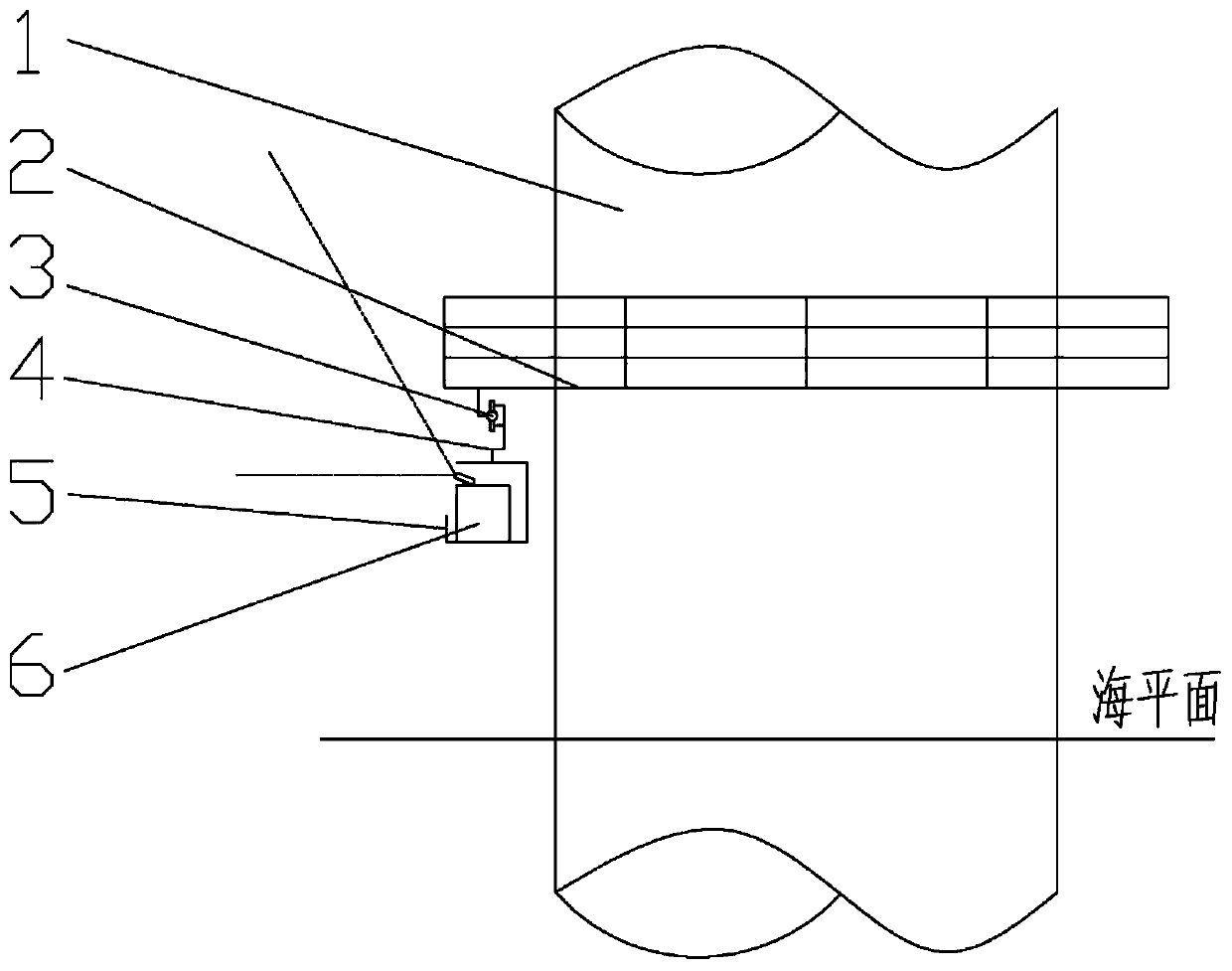
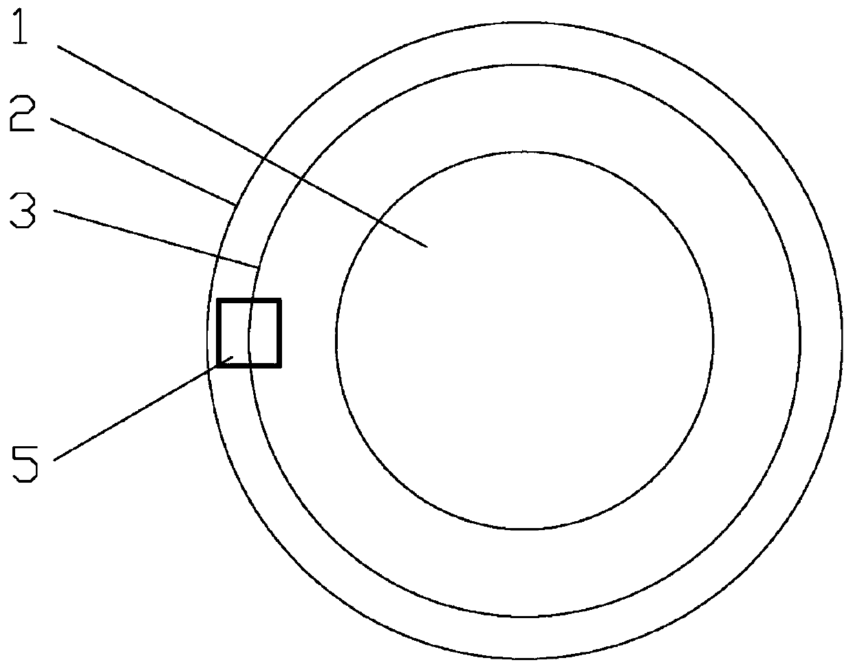
[0047] Such as figure 1 , figure 2 , the offshore scanning laser radar wind measuring device of the present invention includes a wind turbine tower 1, a tower climbing operation platform 2, a slide rail 3, a bracket 4, a radar cabin 5, a scanning laser radar wind measuring instrument 6, a control system and a power system The slide rail 3 is welded below the tower climbing operation platform 2, the slide rail 3 is provided with one, and the support 4 is provided with one; the support 4 is a cantilever structure, and the radar cabin 5 is suspended on the slide rail 3 by the support 4; the slide rail 3, The support 4 and the radar cabin 5 form a structural form similar to a mountain-climbing cable car. The size of the radar cabin 5 is a cube of 2m×2m×2m. The scanning laser radar anemometer 6, the control system and the power system are arranged in the radar cabin and are all fixed with fixing devices. The radar cabin 5 together with the support 4 moves along the slide rail 3...

Embodiment 2

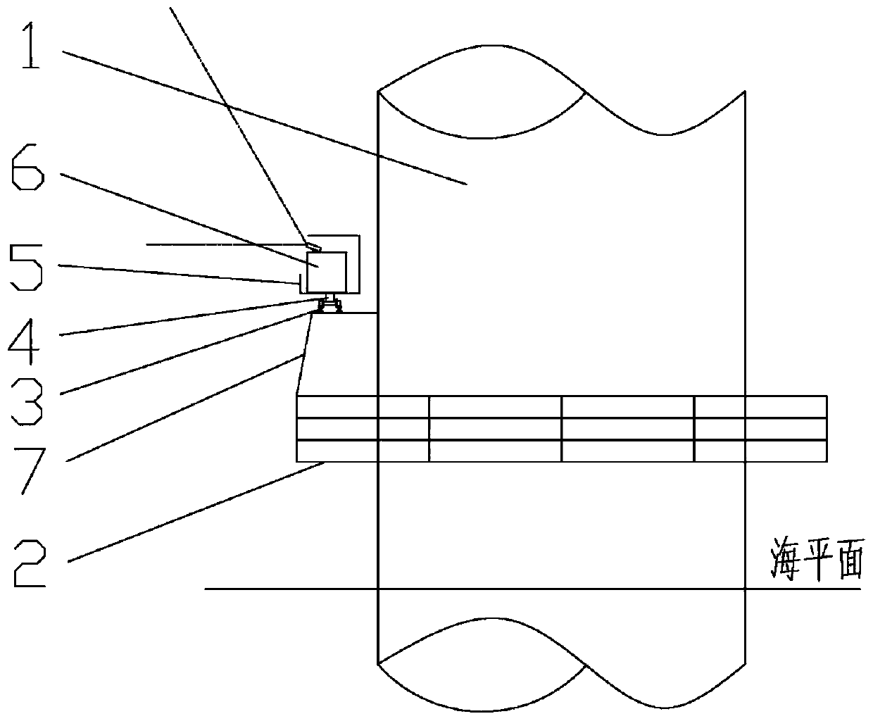
[0049] Such as image 3 , Figure 4 , the offshore scanning laser radar wind measuring device of the present invention comprises a fan tower 1, a tower climbing operation platform 2, a slide rail 3, a bracket 4, a radar cabin 5, a scanning laser radar wind measuring instrument 6, and a slide rail fixing bracket 7 And control system, power system. The slide rail 3 is above the tower climbing operation platform 2, the slide rail 3 is welded on the slide rail fixing bracket 7, the slide rail fixing bracket 7 is welded on the tower climbing operation platform 2, and the slide rail fixing bracket 7 is set around the tower climbing operation platform 2 There are 20 rails to support the weight of the system and keep the system stable. There are two slide rails 3 and two brackets 4. The slide rail 3 is in the shape of an I-shaped steel rail, and there are rollers at the lower end of the bracket 4, which cooperate with the slide rail 3, and the rollers roll along the slide rail 3, an...


PUM


Abstract

The invention discloses an offshore scanning type laser radar wind measuring device and method. The device comprises a tower climbing operation platform, a sliding rail, a support, a radar cabin, a scanning type laser radar wind measuring instrument, a control system and a power system. The sliding rail is arranged on the tower climbing operation platform; the sliding rail is annular and concentric with a fan tower; the scanning type laser radar wind measuring instrument is arranged in the radar cabin; the face, away from the fan tower, of the radar cabin is open; the scanning type laser radarwind measuring instrument and the control system are arranged in the radar cabin; the power system is arranged on the radar cabin; and the output end of the power system is connected with the slidingrail. The annular sliding rail is erected on the basis of an existing tower climbing operation platform of the offshore wind turbine generator, and the cabin provided with the scanning type laser radar wind measuring instrument moves on the sliding rail through roller wheels at the tail end of the support, so that measurement of the wind speed and the wind direction of the space with different heights in the 360-degree range through the laser radar is achieved, and the measurement is not affected by the cabin fixing orientation and the tower shadow effect of a tower drum and is not affected by vibration and shaking of a fan cabin.

Description

technical field [0001] The invention belongs to the technical field of offshore wind power, and in particular relates to an offshore scanning laser radar wind measuring device and method. Background technique [0002] With the development of measurement technology, new wind speed and direction measurement methods are also emerging. In 2017, the IEC released a new version of the IEC61400-12-1 standard, which recognized the wind speed results measured by ground-based lidar, and gave specific regulations for the mutual verification of the measurement results of ground-based lidar and wind measuring towers. [0003] The offshore environment is harsh and complex. Without fixed ground conditions, wind turbines can only be used as a basis for placing lidar. According to the placement location, offshore wind turbine lidar can be divided into lidar arranged on the top of the nacelle and lidar arranged on the foundation of the wind turbine. The laser radar arranged on the top of the...

Claims


Application Information

Patent Timeline
IPC IPC(8): G01S17/58G01S7/48G01S7/481G01P5/26G01S17/95G01P13/02
CPCG01P5/26G01P13/02G01S7/4808G01S7/4817G01S17/58G01S17/95Y02A90/10
Inventor 王绍民唐巍郭小江王茂华陈晓路闫姝谢伟华刘溟江章恂顾健威吴凯朱亚波史绍平
Owner HUANENG GUANYUN CLEAN ENERGY CO LTD
Why Eureka
Try Eureka