Installation parameter calibration device and method for visual tracking assembly

A visual tracking and component installation technology, applied in the field of motion tracking, can solve problems such as failure to meet calibration conditions, failure to consider target installation errors, failure to consider and eliminate unknown or unmodeled error sources, etc., to improve calibration accuracy and improve Tracking accuracy, effects of removing unknown or unmodeled errors

Active Publication Date: 2020-08-04
TIANJIN UNIV
View PDF8 Cites 7 Cited by
  • Summary
  • Abstract
  • Description
  • Claims
  • Application Information

AI Technical Summary

Problems solved by technology

[0005] 1) Only the internal and external parameters of the tracking camera are calibrated separately, generally three-dimensional or two-dimensional plane precision targets are used, and the position and attitude of the target are assumed to be accurately controllable or known, without considering the actual installation error of the target;
[0006] 2) The calculation results of the visual tracking system are not used as calibration feedback information to form a calibration closed loop under normal working mode, and the statistical characteristics of process noise and measurement noise of the tracking system are not considered, and other unknown or unconstructed noise cannot be considered and eliminated. source of error
[0007] 3) Robot hand-eye calibration generally requires the use of end effectors with more rotational degrees of freedom to perform specific movements, which cannot meet the calibration conditions for applications where the camera is installed on a fixed platform
[0008] Therefore, for many especially high-precision motion tracking applications, the current calibration devices and methods cannot meet the requirements of use, and it is necessary to propose new calibration devices and methods for visual tracking systems to obtain accurate installation parameters of visual tracking components

Method used


Image

  • Installation parameter calibration device and method for visual tracking assembly
  • Installation parameter calibration device and method for visual tracking assembly
  • Installation parameter calibration device and method for visual tracking assembly

Examples


Embodiment 1

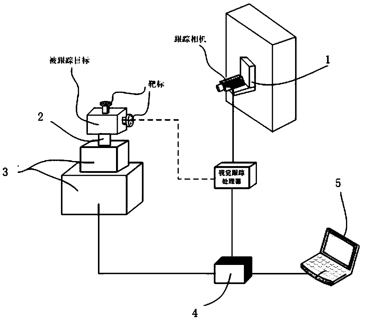
[0054] A calibration device for installation parameters of visual tracking components:

[0055] The device includes a camera mounting bracket 1, a target mounting bracket 2, a two-dimensional turntable 3, a data acquisition module 4, and a calibration computer 5.

[0056] The camera mounting bracket 1 is used to fix the tracking camera so that its optical axis faces a proper direction in the fixed reference coordinate system;

[0057] Several sets of targets are installed on the tracked target, the tracked target is fixed on the two-dimensional turntable 3 through the target mounting bracket 2, and the two-dimensional turntable 3 is fixedly installed in a fixed reference coordinate system;

[0058] The data collection module 4 is used to collect the posture data of the two-dimensional turntable and the posture data output by the visual tracking system;

[0059] The calibration computer 5 is used to control the rotation posture of the two-dimensional turntable 3, receive the data collect...

Embodiment 2

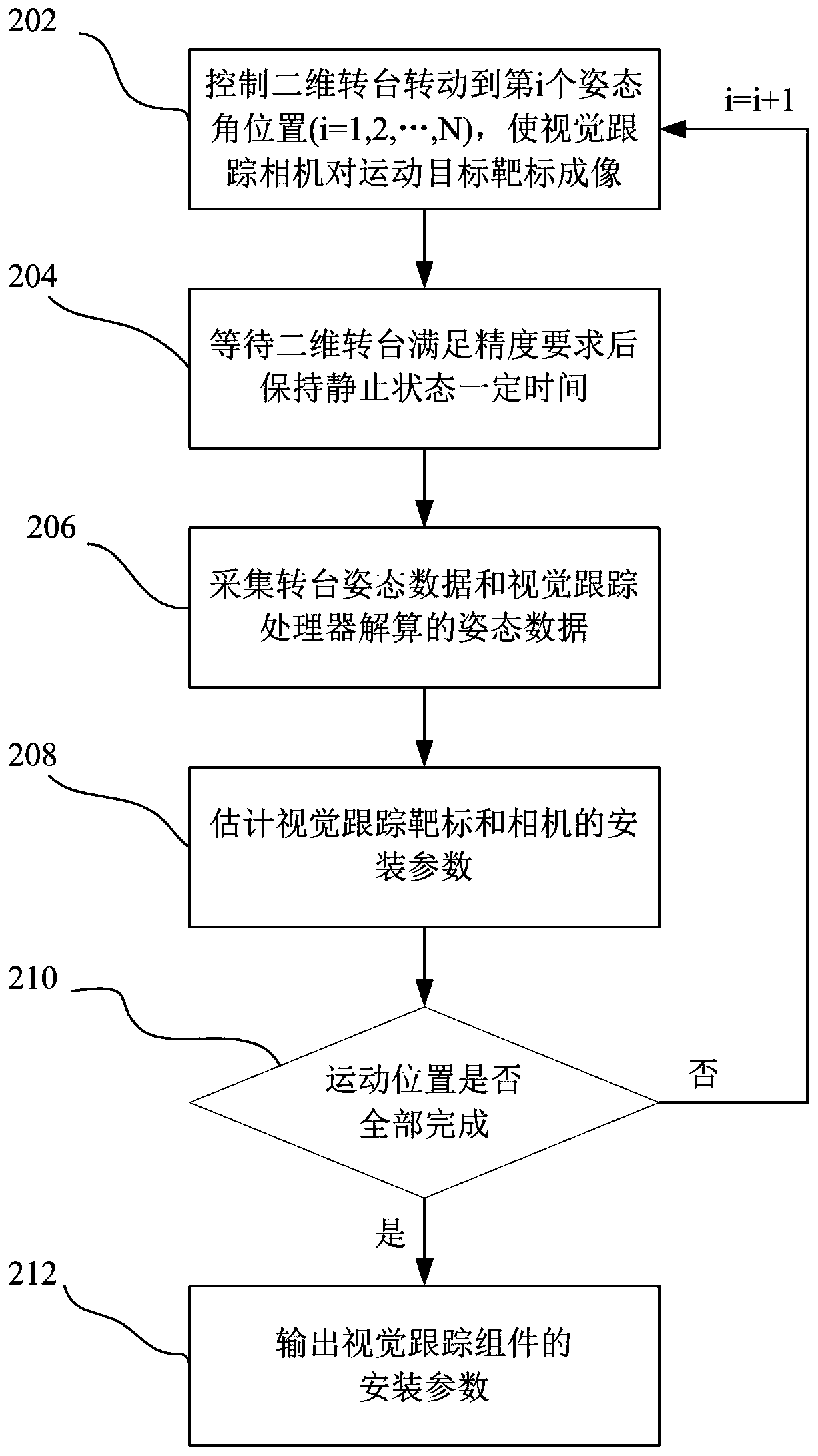
[0061] The method of using the above-mentioned calibration device to calibrate the installation parameters of the visual tracking component is as follows:

[0062] Fix the tracking camera at the normal working position of the environment through the mounting bracket 1, fix the two-dimensional turntable 3 at the center of the normal working range of the environment where the tracked target is located, and fix the tracked target at the second position through the mounting bracket 2. On the dimensional turntable 3, the camera can image the target on the target within a certain movement range of the target.

[0063] Control the two-dimensional turntable 3 to rotate N positions so that the camera can image each group of targets on the target. At each rotation position of the two-dimensional turntable 3, use the data acquisition module 4 to collect the posture data and vision output by the two-dimensional turntable 3 The posture data output by the tracking system, as the two-dimensional ...


PUM


Abstract

The invention discloses an installation parameter calibration device and method for a visual tracking assembly. The device comprises a camera installation support, a target installation support, a two-dimensional turntable, a data acquisition module and a calibration computer. The two-dimensional turntable is controlled to rotate. at each rotating position, a data acquisition module is used for acquiring attitude data of the two-dimensional rotary table and attitude data output by the visual tracking system and sending the data to a calibration computer; the calibration computer converts installation parameter calibration of the visual tracking assembly into state estimation by adopting an extended Kalman filtering algorithm; the installation parameters of the visual tracking assembly to be calibrated are used as state variables, attitude data output by the two-dimensional turntable are converted, obtained attitude matrix elements are used as measurement vectors, and a first-order linearized measurement matrix is constructed by using attitude calculation data of a visual tracking system and the state variables at the last moment. A visual tracking system is introduced into the calibration process to form a closed loop, so that unmodeled errors can be eliminated, and the calibration precision is improved.

Description

Technical field [0001] The invention belongs to the motion tracking technology in the fields of robots and VR / AR, and relates to a device and method for calibration of installation parameters of visual tracking components. Background technique [0002] Motion tracking technology is one of the important research contents in the fields of robotics and VR / AR. It is used to determine the movement information of the moving target relative to the environment in which it is located. The visual tracking system is to install the visual tracking camera in the environment, install the pre-designed pattern on the moving target or use the characteristics of the moving target as the tracking target. When the target is moving, the visual camera is used to image the target on the target Detection, through image processing and visual algorithm solution, real-time tracking of the position and attitude change information of the moving target relative to the environment. [0003] The visual tracking ...

Claims


Application Information

Patent Timeline
Patent Type & Authority Applications(China)
IPC IPC(8): G06T7/80
CPCG06T7/80
Inventor 彭慧伶孙长库王鹏
Owner TIANJIN UNIV
Why Eureka
Try Eureka