
Alternating current distribution equipment automatic control device based on bimetallic strip principle

An automatic control device, AC power distribution technology, applied in substation/distribution device housing, automatic disconnection emergency protection device, circuit device, etc., can solve the problem of slow response to circuit overload, damage to internal components of equipment, and space occupied by cabinets Large and other problems, to achieve the effect of timely response to circuit overload, avoiding equipment damage, and good fire extinguishing effect

Inactive Publication Date: 2020-08-04
杭州千耘贸易有限公司
View PDF0 Cites 4 Cited by
  • Summary
  • Abstract
  • Description
  • Claims
  • Application Information

AI Technical Summary

Problems solved by technology

[0003] However, the existing AC power distribution equipment usually has a square cabinet structure, which leads to a large space occupied by the cabinet and low space utilization, and the existing AC power distribution equipment usually uses fuses for circuit monitoring, resulting in slow response to circuit overload , it is easy to cause damage to the internal components of the equipment, and it is troublesome to replace, which leads to certain limitations in use, and the existing AC power distribution equipment often only has control circuit disconnection and equipment fire alarm devices, but when the equipment has caught fire, it is often not equipped with corresponding Fire extinguishing device, so that the fire spreads, increases the number and degree of damage to electrical components, and easily leads to an increase in the scope of the fire, thereby causing the risk of fire

Method used


Image

  • Alternating current distribution equipment automatic control device based on bimetallic strip principle
  • Alternating current distribution equipment automatic control device based on bimetallic strip principle
  • Alternating current distribution equipment automatic control device based on bimetallic strip principle

Examples


Embodiment Construction

[0027] The following will clearly and completely describe the technical solutions in the embodiments of the present invention with reference to the accompanying drawings in the embodiments of the present invention. Obviously, the described embodiments are only some, not all, embodiments of the present invention. Based on the embodiments of the present invention, all other embodiments obtained by persons of ordinary skill in the art without making creative efforts belong to the protection scope of the present invention.

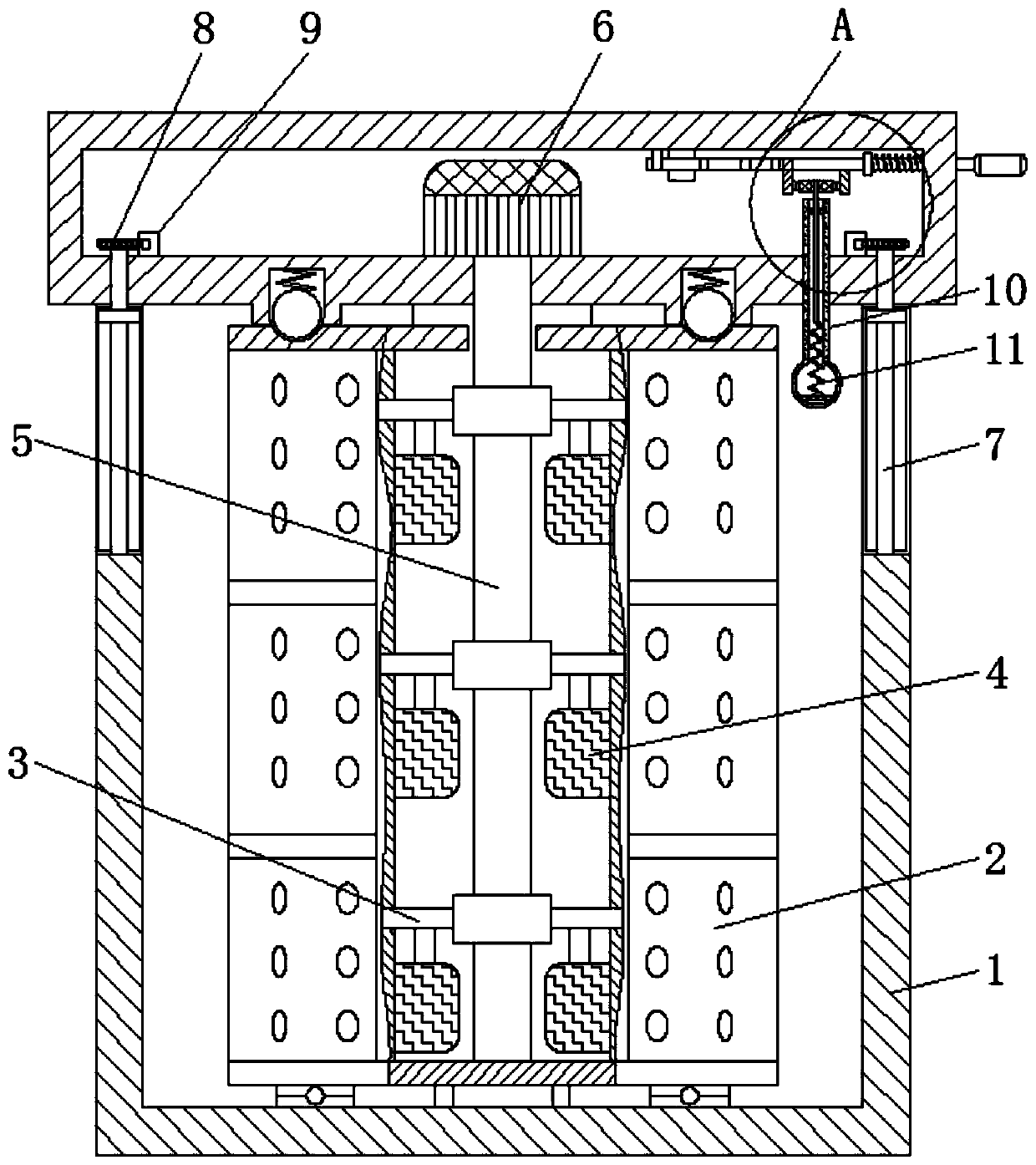
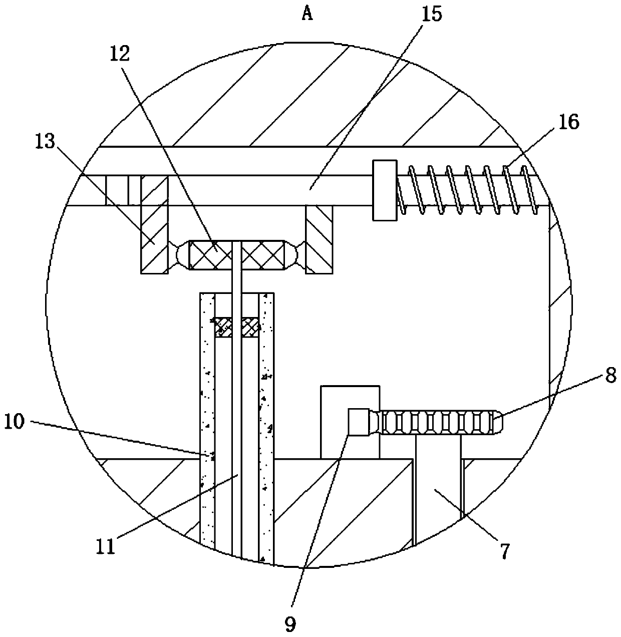
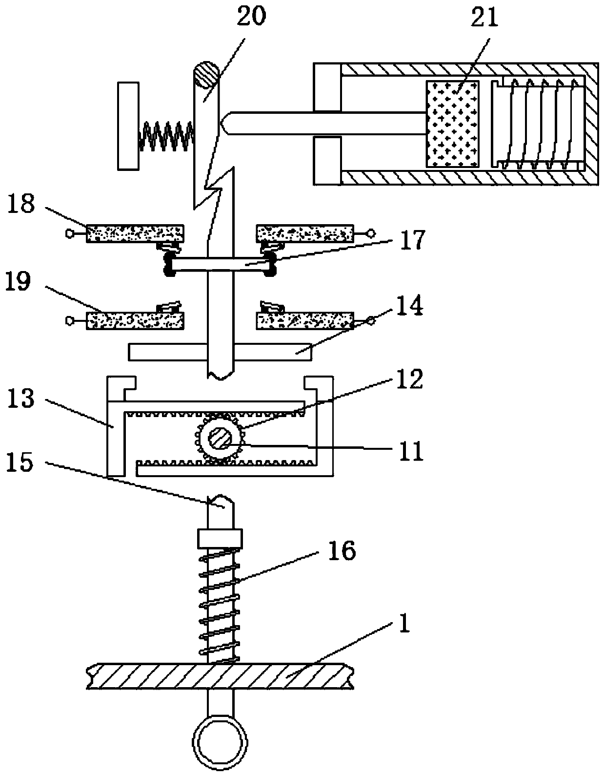
[0028] see Figure 1-4 , an automatic control device for AC power distribution equipment based on the principle of bimetal sheets, including a cabinet body 1, a mounting frame 2, a branch pipe 3, a dry powder tank 4, a main pipe 5, an air compressor 6, a sealing plate 7, a sealing gear 8, Sealed motor 9, housing 10, bimetal rod 11, control gear 12, control gear rod 13, stop rod 14, control rod 15, return spring 16, connection block 17, first contact block 18, ...


PUM


Abstract

The invention relates to the technical field of AC power distribution equipment, and discloses an alternating-current power distribution equipment automatic control device based on a bimetallic stripprinciple. The control device comprises a cabinet body, the interior of the cabinet body is rotatably connected with a mounting frame. A branch pipe is fixedly connected to the interior of the mounting frame; the exterior of the branch pipe is fixedly connected with a dry powder tank; the outer part of the branch pipe is rotationally connected with a main pipeline; the outer part of the main pipeline is fixedly connected with a wind pressure machine; the interior of the cabinet body is movably connected with a sealing plate. The top of the sealing plate is fixedly connected with a sealing gear; a sealing motor is movably connected to the outer part of the sealing gear; the interior of the cabinet body is fixedly connected with a shell. A bimetal rod is movably connected to the interior ofthe shell, a control gear is fixedly connected to the top of the bimetal rod, and through cooperative use of the cabinet body and the mounting frame, space occupation of the equipment is reduced, thespace utilization rate of the equipment is increased, space waste is reduced, and the equipment is effectively and conveniently mounted and stored.

Description

technical field [0001] The invention relates to the technical field of AC power distribution equipment, in particular to an automatic control device for AC power distribution equipment based on the bimetal principle. Background technique [0002] AC power distribution equipment is used to connect power supply, transformer, converter equipment and other loads, and monitor and protect the power supply system. The control functions of the operation mode, such as protection, measurement, alarm and power factor compensation, etc. [0003] However, the existing AC power distribution equipment usually has a square cabinet structure, which leads to a large space occupied by the cabinet and low space utilization, and the existing AC power distribution equipment usually uses fuses for circuit monitoring, resulting in slow response to circuit overload , it is easy to cause damage to the internal components of the equipment, and it is troublesome to replace, which leads to certain limi...

Claims


Application Information

Patent Timeline
Patent Type & Authority Applications(China)
IPC IPC(8): H01H71/16H02B1/28H02H5/04A62C3/16
CPCA62C3/16H01H71/16H02B1/28H02H5/047
Inventor 穆之栋
Owner 杭州千耘贸易有限公司
Learn More