Rotary installation structure and installation method of battery pack
A technology for installing structures and battery packs, applied in structural parts, battery pack parts, circuits, etc., can solve problems such as affecting the normal use of power devices, small contact area between connecting electrodes, and electrodes being prone to heat and safety accidents, and achieve contact The effect of low resistance, good contact and high reliability
- Summary
- Abstract
- Description
- Claims
- Application Information
AI Technical Summary
Problems solved by technology
Method used
Image
Examples
Embodiment 1
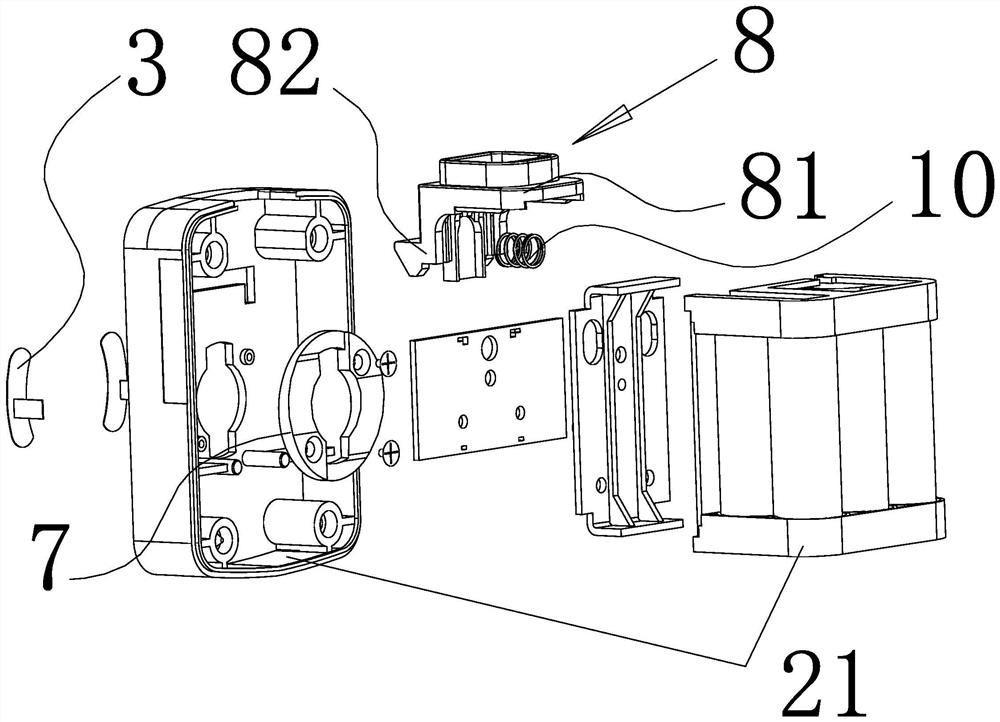
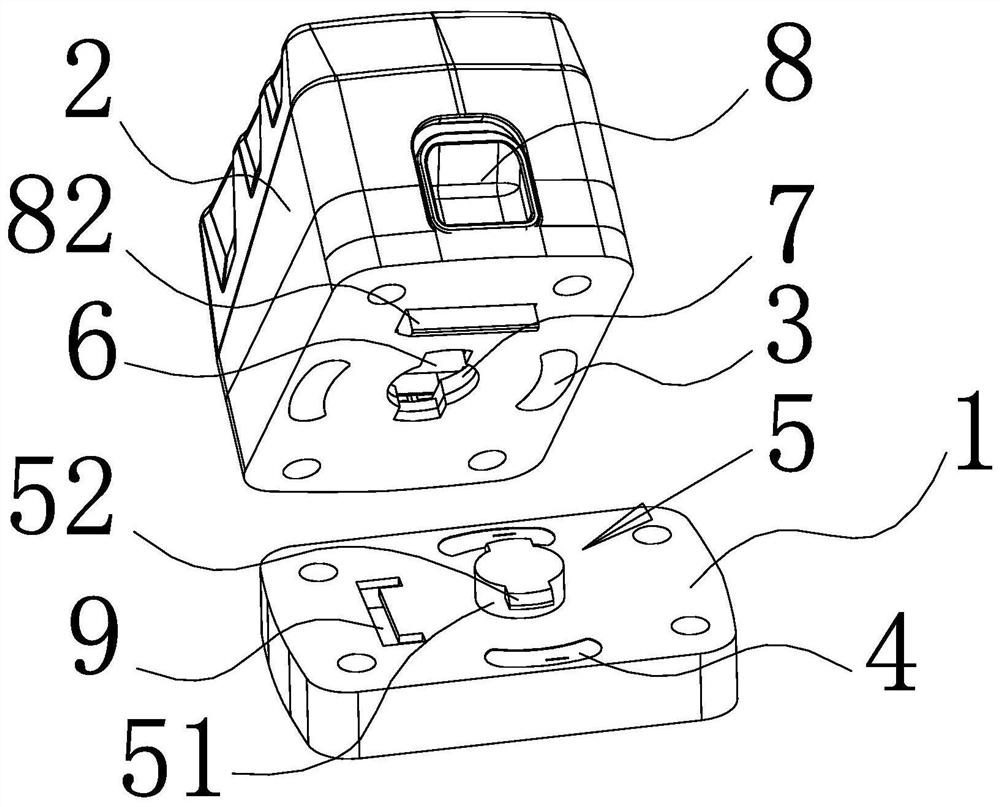
[0027] like figure 1 and figure 2 As shown, a rotary installation structure of a battery pack of the present invention includes a power unit 1 and a battery pack 2 movably connected to the power unit 1. For better description, the power unit 1 in this embodiment is a portable The power tool, wherein the battery pack 2 is electrically connected to a pair of power electrodes 4 of the power device 1 through a pair of battery pack electrodes 3 correspondingly, and a positioning hook 5 is provided in the middle of the docking surface of the power device 1, which is connected with the positioning hook. 5. A positioning slot 6 is opened on the outer casing 21 of the corresponding battery pack 2. The battery pack electrode 3 and the power electrode 4 are arc-shaped members with the same shape and size, and the battery pack electrode 3 is located on both sides of the positioning slot 6. , the power electrodes 4 are located on both sides of the positioning hook 5, and the two battery ...
Embodiment 2
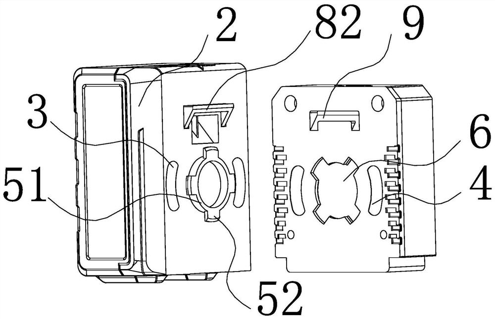
[0034] like image 3 As shown, a positioning hook 5 is provided in the middle of the butting surface of the outer casing 21 , and a positioning hook 6 is opened on the abutting surface of the power device 1 corresponding to the positioning hook 5 . The rest is exactly the same as in Example 1.
Embodiment 3
[0036] like Figure 4 and Image 6 As shown, the outer ring surface corresponding to the outer end of the positioning column 51 is integrally extended outward to form four square positioning bosses 52 , and the inner side surface of the anti-loose washer 7 corresponding to the positioning bosses 52 extends toward the interior of the battery pack 2 to form There are four spherical elastic bumps 62, and the height of the elastic bumps 62 is 0.5 mm to 1 mm. When locking, the positioning hook 5 is hooked on the corresponding elastic bumps 62 through the positioning bumps 52, in order to prevent the locking position from being deviated. , the limit posts 11 are set at the initial locking position, and the limit posts 11 are all located on the inner wall surface of the outer casing 21, wherein the anti-loose washer 7 is made of metal material, and the anti-loose washer 7 and the outer casing of the battery pack 2 21 A spring washer is installed between the inner walls. This embodi...
PUM
| Property | Measurement | Unit |
|---|---|---|
| height | aaaaa | aaaaa |
Abstract
Description
Claims
Application Information
 - R&D
- Intellectual Property
- Life Sciences
- Materials
- Tech Scout
- Unparalleled Data Quality
- Higher Quality Content
- 60% Fewer Hallucinations
Browse by: Latest US Patents, China's latest patents, Technical Efficacy Thesaurus, Application Domain, Technology Topic, Popular Technical Reports.
© 2025 PatSnap. All rights reserved.Legal|Privacy policy|Modern Slavery Act Transparency Statement|Sitemap|About US| Contact US: help@patsnap.com


