Temperature detection method of permanent magnet synchronous motor

A technology of permanent magnet synchronous motor and detection method, which is applied in the direction of motor control, electrical components, control system, etc., can solve the problems of motor speed and torque ripple, poor feasibility of temperature detection, affecting calculation accuracy, etc., to achieve accurate temperature monitoring, High accuracy and low cost effect

Pending Publication Date: 2020-08-04
东南大学深圳研究院
View PDF6 Cites 3 Cited by
  • Summary
  • Abstract
  • Description
  • Claims
  • Application Information

AI Technical Summary

Problems solved by technology

[0003] So far, several methods have been proposed for estimating the temperature of the motor. 1) Simplified formula method: This method can only estimate the overall core temperature or the average temperature rise of the winding, so the calculation result is relatively rough, and it is applied to the temperature Poor detection feasibility; 2) Equivalent thermal circuit method: can only calculate the average temperature rise of some windings and cores; 3) Numerical calculation method: This method has high calculation accuracy, but it depends on the structural parameters of the motor and the materials used 4) Parameter identification method: This method has the characteristics of simplicity and practicality, but it can only give the temperature of the motor winding in normal steady state operation; 5) Thermal model method: The method's The calculation accuracy is high, but the change of the thermal parameters of the motor will cause the failure of the thermal model to estimate the temperature; 6) Resistance method: the temperature of the motor is estimated indirectly by estimating the motor resistance. This method is simple and is not affected by the change of the motor parameters. It is more and more favored by people, among which the stator resistance estimation method based on DC injection method is the most popular
However, some current injection methods will cause the motor speed (or torque) to fluctuate, affecting the accuracy of the calculation

Method used


Image

  • Temperature detection method of permanent magnet synchronous motor
  • Temperature detection method of permanent magnet synchronous motor
  • Temperature detection method of permanent magnet synchronous motor

Examples


Embodiment Construction

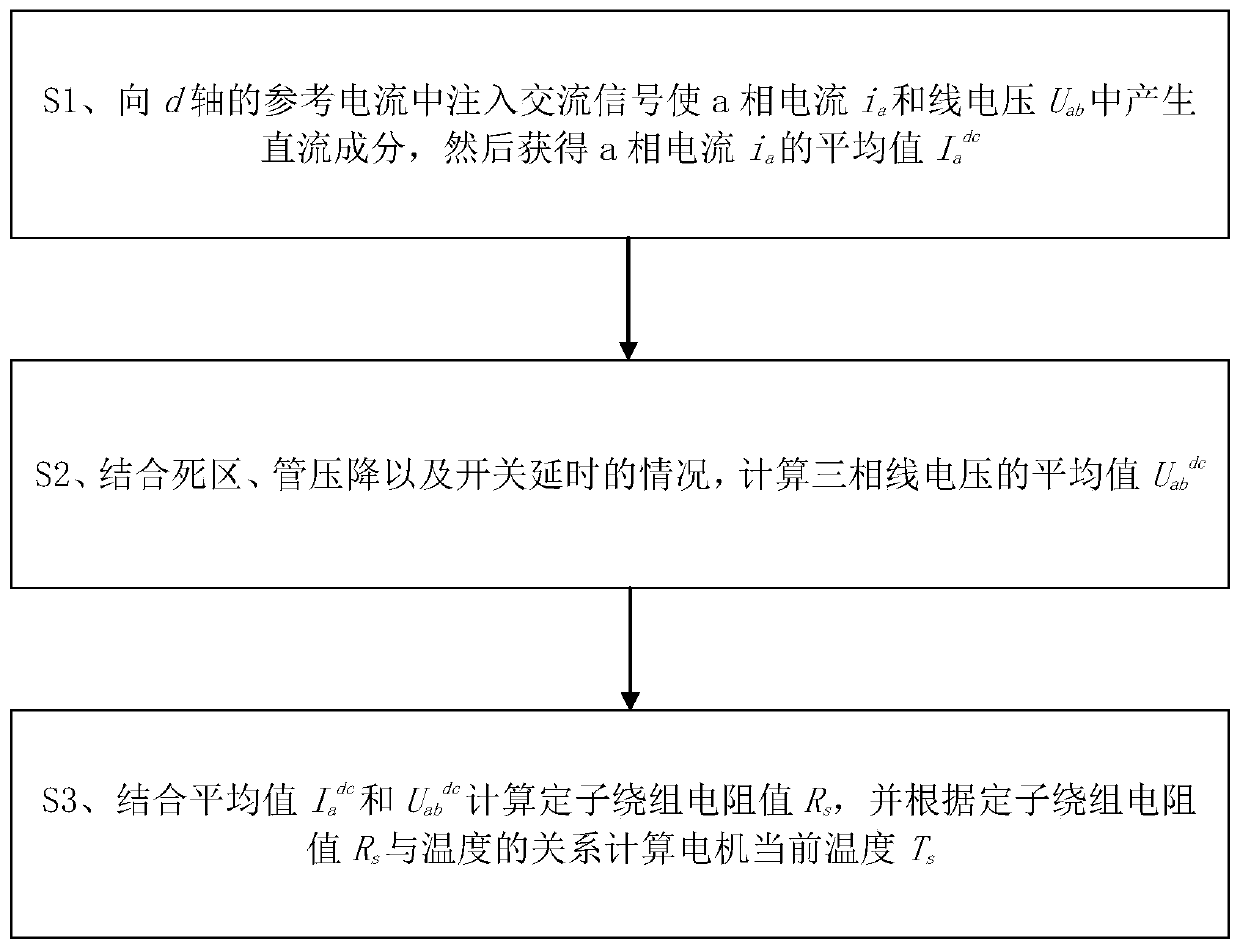
[0023] refer to figure 1 A method for detecting the temperature of a permanent magnet synchronous motor proposed by the present invention includes the following steps.

[0024] S1. Inject an AC signal into the reference current of the d-axis to make the a-phase current i a and line voltage U ab A DC component is generated in the middle, and then the a-phase current i is obtained a the average value of I a dc . During specific implementation, the duty cycle of the PWM signal and the DC bus voltage U dc .

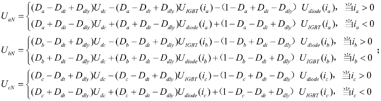
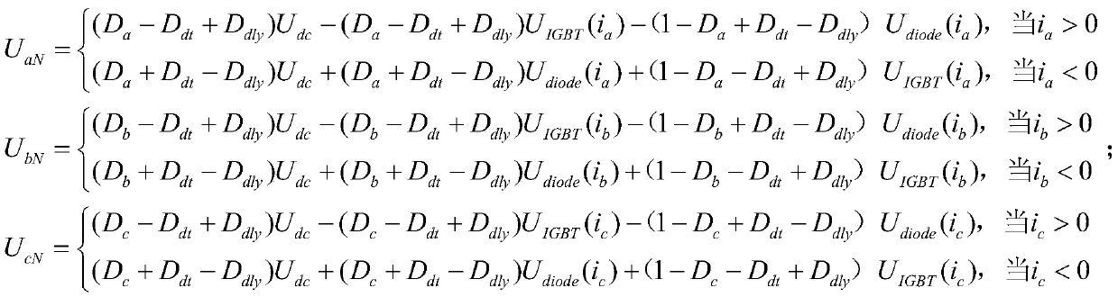
[0025] S2. Calculate the average value U of the three-phase line voltage in combination with the dead zone, tube voltage drop and switch delay ab dc .

[0026] Specifically, in this step, the average value U of the three-phase voltage is calculated by using the duty cycle of the PWM signal and the DC bus voltage in combination with the dead zone, the tube voltage drop and the switching delay. ab dc .

[0027] S3, combined with the average value I a dc and U ab ...


PUM


Abstract

The invention provides a temperature detection method for a permanent magnet synchronous motor, and the method comprises the following steps: injecting an AC signal into a d-axis reference current, enabling an a-phase current ia and a line voltage Uab to generate a DC component, and then obtaining an average value Iadc of the a-phase current ia; calculating an average value Uabdc of the three-phase line voltage by combining the dead zone, the tube voltage drop and the switch delay; and calculating the resistance value Rs of a stator winding by combining the average value Iadc and the average value Uabdc, and calculating the current temperature Ts of the motor according to the relationship between the resistance value Rs of the stator winding and the temperature. According to the temperature detection method of the permanent magnet synchronous motor, only the alternating current signal needs to be injected into the reference current of the d axis, disturbance to the torque of the motoris avoided, and temperature monitoring of the permanent magnet motor is more accurate.

Description

technical field [0001] The invention relates to the technical field of permanent magnet synchronous motors, in particular to a temperature detection method for permanent magnet synchronous motors. Background technique [0002] The temperature rise of the permanent magnet synchronous machine (PMSM) during operation will lead to the demagnetization of the permanent magnet, damage the insulation of the winding, and directly affect the reliable operation and life of the motor. Accurate detection of motor temperature rise can not only ensure the safe operation of the motor, but also improve the service life of the motor. Therefore, it is of great practical significance to carry out temperature detection of permanent magnet synchronous motors. [0003] So far, several methods have been proposed for estimating the temperature of the motor. 1) Simplified formula method: This method can only estimate the overall core temperature or the average temperature rise of the winding, so the...

Claims


Application Information

Patent Timeline
Patent Type & Authority Applications(China)
IPC IPC(8): H02P29/64
CPCH02P29/64
Inventor 杭俊丁石川丁敏汤春艳
Owner 东南大学深圳研究院
Why Eureka
Try Eureka