
Mask lining steel wire sectioning device and using method thereof

A technology of steel wire cutting and lining, applied in clothing, application, clothing and other directions, can solve the problems of no auxiliary grinding structure, increase maintenance cost, decrease in sharpness, etc., to avoid the phenomenon of different lengths, improve processing effect, The effect of avoiding device blocking

Active Publication Date: 2020-08-07
ANHUI HENGYI TEXTILE TECH CO LTD
View PDF13 Cites 0 Cited by
  • Summary
  • Abstract
  • Description
  • Claims
  • Application Information

AI Technical Summary

Problems solved by technology

[0004] The existing mask lining steel wire cutting device has certain disadvantages during use. The traditional mask lining steel wire cutting device only has a single cutting function, so that it can only cut the steel wire. Adding raw materials in this way reduces the working efficiency of the mask lining steel wire cutting device, making it unable to perform automatic material addition operations. Secondly, the traditional mask lining steel wire cutting device does not have a continuous truncation structure, which makes the traditional mask lining steel wire cutting The section device cannot continuously cut off the steel wire raw material, which reduces the flexibility of the mask lining steel wire cutting device. At the same time, the traditional mask lining steel wire cutting device does not have an auxiliary grinding structure, which makes the traditional mask lining steel wire cutting device After a long time of use, the sharpness decreases, which increases its maintenance cost and brings certain adverse effects to users.

Method used


Image

  • Mask lining steel wire sectioning device and using method thereof
  • Mask lining steel wire sectioning device and using method thereof
  • Mask lining steel wire sectioning device and using method thereof

Examples


Embodiment Construction

[0033] The technical solutions in the embodiments of the present invention will be clearly and completely described below in conjunction with the embodiments of the present invention. Apparently, the described embodiments are only some of the embodiments of the present invention, not all of them. Based on the embodiments of the present invention, all other embodiments obtained by persons of ordinary skill in the art without creative efforts fall within the protection scope of the present invention.

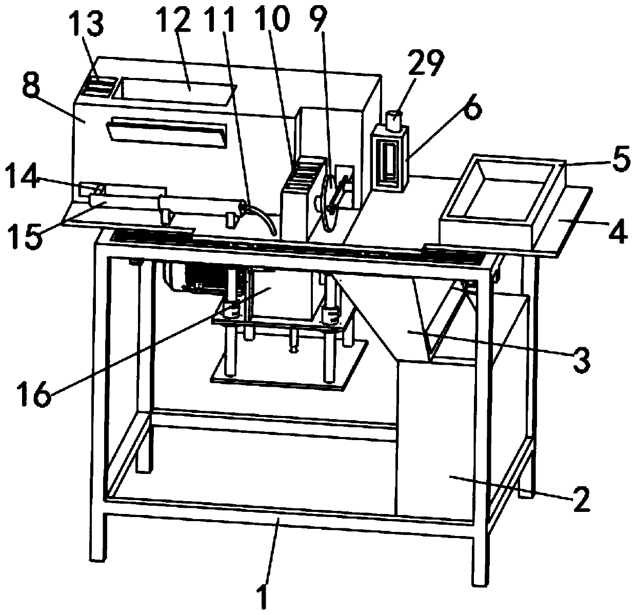
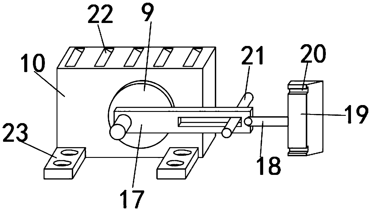
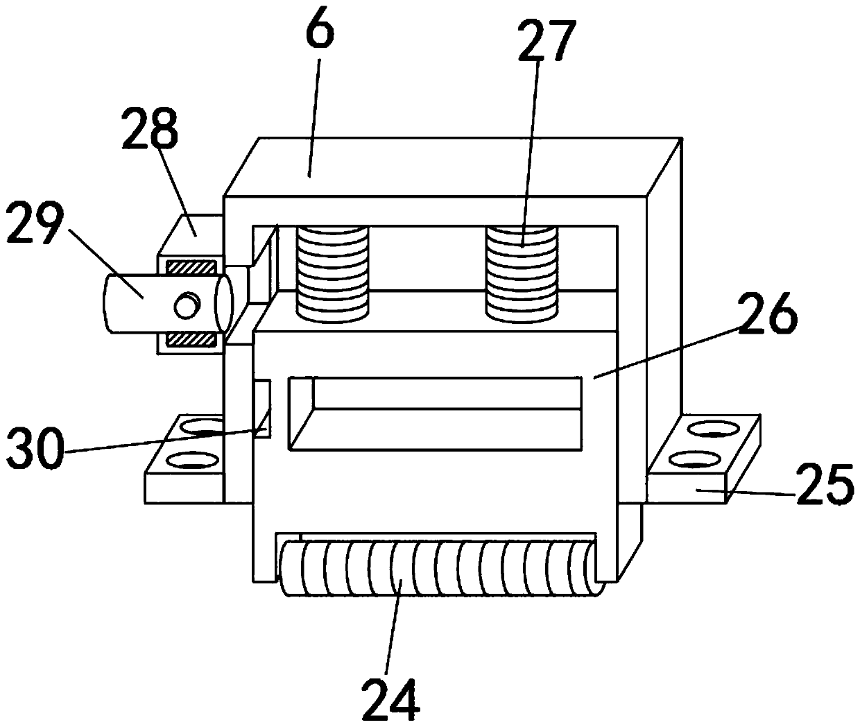
[0034] like Figure 1-6 As shown, a mask lining steel wire cutting device includes a fixed base plate 4, a material holding box 8 and a fixed frame 1, the material holding box 8 is fixedly installed on the upper surface of the fixed base plate 4, and the upper end of the fixed base plate 4 is close to the material. The front portion of the box 8 is fixedly installed with a first motor 10, and the side of the first motor 10 is movably equipped with an eccentric wheel 9, and a trans...


PUM


Abstract

The invention discloses a mask lining steel wire sectioning device. The device comprises a fixed bottom plate, a material containing box and a fixed frame, and the material containing box is fixedly installed on the outer surface of the upper end of the fixed bottom plate. A first motor is fixedly mounted at the front part, close to the material containing box, of the upper end of the fixed bottomplate; an eccentric wheel is movably mounted on the side edge of the first motor; a transmission arm is movably mounted on the eccentric wheel; the inner side of the transmission arm is movably sleeved with a positioning guide rod; the positioning guide rod is fixedly installed on the inner side of the material containing box, a material cutting tool bit is movably installed at one end of the transmission arm, the transmission arm and the material cutting tool bit are movably connected through a linkage rod, two sets of limiting clamping grooves are formed in the inner surface of the inner side of the material cutting tool bit, and a feeding groove is formed in the inner surface of the inner side of the material containing box. The mask lining steel wire sectioning device is provided withan automatic feeding structure, the working efficiency of the mask lining steel wire sectioning device is improved, meanwhile, the mask lining steel wire sectioning device is provided with an auxiliary grinding structure, self functionality is improved, and use is convenient.

Description

technical field [0001] The invention belongs to the technical field of section cutting devices, in particular to a section cutting device for steel wires lined with masks. Background technique [0002] The mask lining steel wire cutting device is a cutting device that cuts off the steel wire structure inside the mask during the production and processing of the mask, so that the steel wire material is processed into segmental structures of equal size. It is a steel wire structure that is placed in the mask and fixes the bridge of the user's nose when the user wears the mask. [0003] A section cutting device disclosed in the comparative document CN109159213A includes a chain saw arranged at the discharge end of the guide chain, the length direction of the chain saw is perpendicular to the discharge end of the guide chain, and the discharge end of the guide chain is above the discharge end. A compression mechanism is also provided, and the chain saw moves up and down correspo...

Claims


Application Information

Patent Timeline
Patent Type & Authority Applications(China)
IPC IPC(8): A41H43/02A41D13/11
CPCA41D13/11A41H43/02
Inventor 李贺
Owner ANHUI HENGYI TEXTILE TECH CO LTD
Learn More