Steel mill waste gas emission environment protection treatment system

A waste gas emission and environmental protection treatment technology, which is applied in the direction of cleaning hollow objects, combined devices, cleaning methods and appliances, etc., can solve the problems of the influence of the filtering structure on the filtering effect, the low degree of impurity filtration and adsorption, ignoring the use of heat energy of the waste gas, etc., so as to avoid Decrease or loss of adsorption capacity, reduce the effect of poor connection sealing, and facilitate installation and disassembly for cleaning

Inactive Publication Date: 2020-08-07
魏庆
View PDF4 Cites 0 Cited by
  • Summary
  • Abstract
  • Description
  • Claims
  • Application Information

AI Technical Summary

Problems solved by technology

[0003] 1. In the waste gas treatment method, it is usually considered to filter and adsorb the impurities in the waste gas. In this process, the external power drive structure is basically used, and the utilization of the heat energy of the waste gas itself is often ignored. At the same time, the waste gas contains The forms of impurities are different, and a relatively simple filter structure is commonly used, so that the degree of filtration and adsorption of impurities in the exhaust gas is low;
[0004] 2. Part of the impurities entrained by the exhaust gas will accumulate on the inside of the channel and the filter structures contained in the channel. The accumulated impurities will form a thicker impurity layer after a long time, and the impurity layer is easy to operate and filter between structures. The filtering effect of the structure is affected, and the common exhaust gas channel adopts an integrated structure, which is not conducive to cleaning the channel regularly

Method used


Image

  • Steel mill waste gas emission environment protection treatment system
  • Steel mill waste gas emission environment protection treatment system
  • Steel mill waste gas emission environment protection treatment system

Examples


Embodiment Construction

[0034] The embodiments of the present invention will be described in detail below with reference to the accompanying drawings, but the present invention can be implemented in a variety of different ways predetermined and covered by the claims.

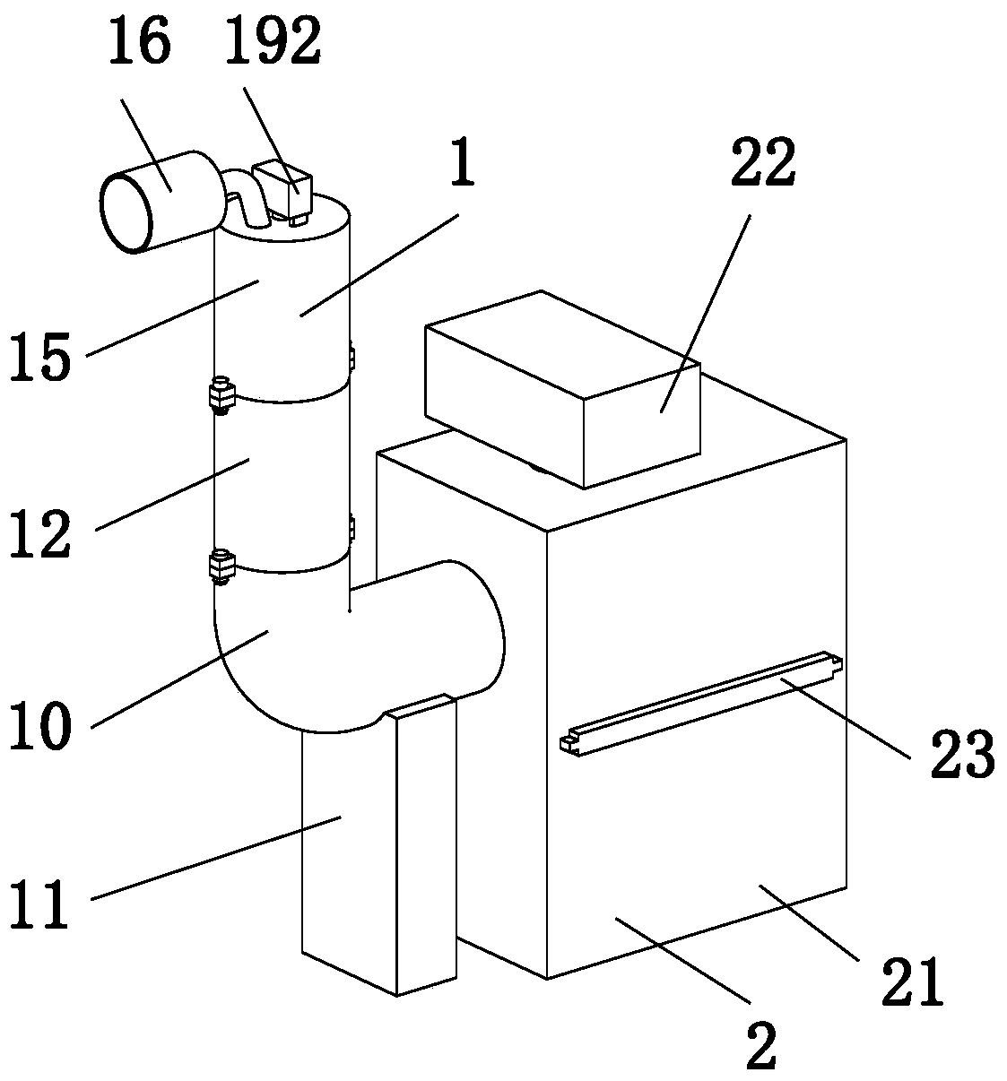
[0035] Such as Figure 1 to Figure 11 As shown, an environmental protection treatment system for waste gas emissions from a steelmaking plant includes a filtering mechanism 1 and a liquefaction mechanism 2. The right end of the filtering mechanism 1 is connected with a liquefaction mechanism 2, and the lower end of the liquefaction mechanism 2 is installed on an existing work ground.

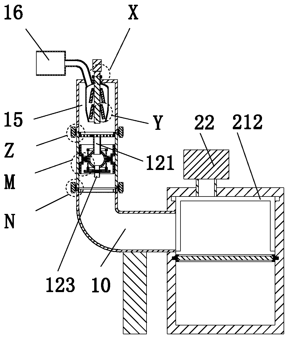
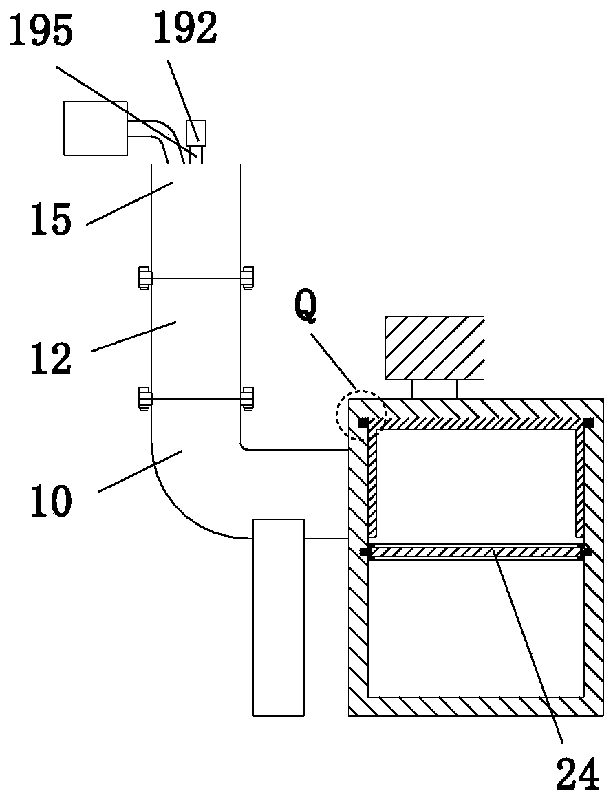
[0036] The filter mechanism 1 includes an L-shaped pipe 10, a support seat 11, a No. 1 pipe 12, a No. 1 bump 13, a No. 1 bolt 14, a No. 2 pipe 15, an intake pipe 16, a No. 2 bump 17, and a No. 2 bolt 18 and the filter cleaning group 19, the right end of the L-shaped tube 10 and the left end of the liquefaction mechanism 2 are connected by threaded fitting, th...


PUM


Abstract

The invention relates to a steel mill waste gas emission environmental protection treatment system, which comprises a filtration mechanism and a liquefaction mechanism, the right end of the filtrationmechanism is connected with the liquefaction mechanism, and the lower end of the liquefaction mechanism is installed on the existing working ground; the filtration mechanism comprises an L-shaped pipe, a supporting base, a first pipeline, a first protruding block, a first bolt, a second pipeline, an air inlet pipe, a second protruding block, a second bolt and a filtering and cleaning set. The design concept of a filtering-cleaning integrated structure is adopted for environment-friendly treatment of steel mill waste gas emission; the initial end and the tail end of the waste gas flowing pathare each provided with a structure with a filtering function so that waste gas can be subjected to multi-stage filtering and impurity adsorption treatment, meanwhile, a plurality of cleaning structures are arranged so that the structures with impurities attached to the surface area can be removed, and the situation that operation between the structures is affected due to excessive impurities accumulated in the system is reduced.

Description

Technical field [0001] The invention relates to the technical field of steel-making waste gas treatment, in particular to a steel-making plant waste gas emission environmental protection treatment system. Background technique [0002] Steel mills are heavy industry, secondary industry, manufacturing, capital-intensive industries, fixed assets, factory types, and raw materials for steel mills are iron ore, coal, charcoal, etc., which are supplied by the mining industry. Because steel plants are the production of strategic materials, most countries are state-owned enterprises. Their main task is to desulfurize, dephosphorize, decarburize, and deoxidize molten iron, and then cast molten steel into billets. Steelmaking refers to the use of pig iron to release Smelt according to a certain process in the steelmaking furnace, control the carbon content (generally less than 2%), eliminate harmful elements such as P, S, O, and N, retain or increase beneficial elements such as Si, Mn, Ni, ...

Claims


Application Information

Patent Timeline
Patent Type & Authority Applications(China)
IPC IPC(8): B01D50/00B01D53/00B08B9/055
CPCB01D50/00B01D53/002B08B9/0557
Inventor 魏庆朱乐乐
Owner 魏庆
Why Eureka
Try Eureka