
Stable cotton yarn spinning machine

A textile machine and cotton yarn technology, applied in the textile field, can solve the problems of burrs, entanglement, and entanglement of cotton threads, and achieve the effect of avoiding excessive friction

Active Publication Date: 2020-08-07
佛山市森洋纺织实业有限公司
View PDF8 Cites 0 Cited by
  • Summary
  • Abstract
  • Description
  • Claims
  • Application Information

AI Technical Summary

Problems solved by technology

[0003] Based on the above inventors' discovery, the existing stable cotton yarn spinning machine mainly has the following disadvantages, such as: the cotton thread is collected by the winding roller and needs to be guided by the guide roller, and when it is dry, the cotton thread is easily rubbed on the guide roller. Static electricity is generated, so that burrs will appear on the cotton thread, and the cotton thread will be pressed against the burrs when it is wound, causing the cotton thread and burrs to be entangled together, and cotton thread entanglement occurs

Method used


Image

  • Stable cotton yarn spinning machine
  • Stable cotton yarn spinning machine
  • Stable cotton yarn spinning machine

Examples


Embodiment 1

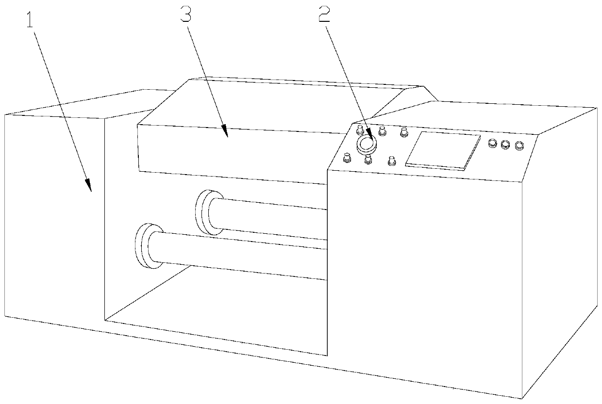
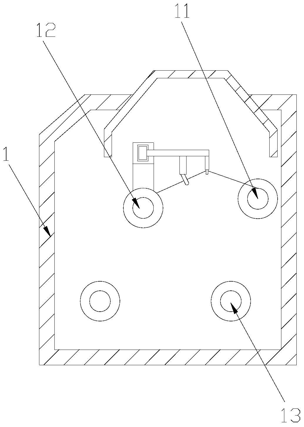
[0029] Example 1: Please refer to Figure 1-Figure 6 The specific embodiment of the present invention is as follows: its structure includes a main body 1, a top cover 2, and a control panel 3. The top cover 2 is embedded in the middle of the top of the main body 1, and the control panel 3 is located at the top side of the main body 1; The main body 1 includes a drum 11, a winding roller 12, and a wire waste roller 13, the drum 11 is installed on the top rear end of the main body 1, and it is characterized in that: the winding roller 12 is embedded in the top front end of the main body 1, Two wire waste rollers 13 are provided, and the wire waste rollers 13 are installed at the bottom of the main body 1 .

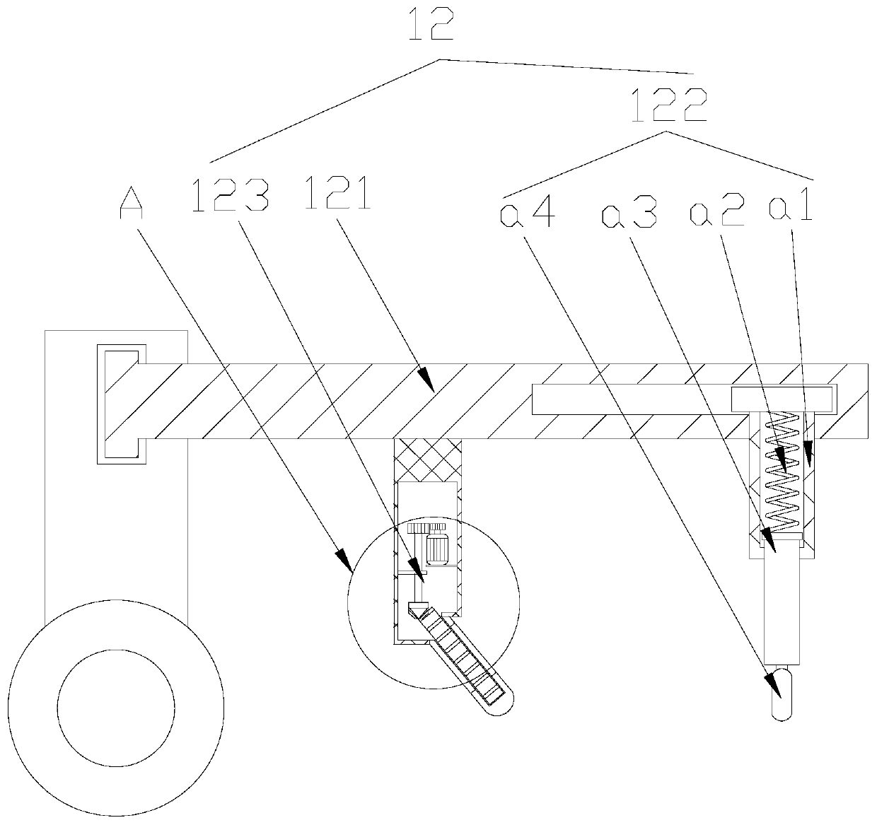
[0030] Include support column 121, wire device 122, hair removal device 123 in the described winding roller 12, described support column 121 is welded on the both sides of winding roller 12, and described wire device 122 is installed on the end of support column 121, so The...

Embodiment 2

[0036] Example 2: Please refer to Figure 7-Figure 9 The specific embodiment of the present invention is as follows: the hair removal device 123 includes a fixed column c1, a motor c2, and a hair removal block c3, and a motor c2 is installed inside the fixed column c1, and the motor c2 in the fixed column c1 is vertical Installation, the hair removal block c3 is arranged at the bottom of the fixed column c1, the angle between the hair removal block c3 and the fixed column c1 is 120 degrees, and the motor c2 is movably matched with the hair removal block c3, which is beneficial to the Cotton thread for hair removal.

[0037]The hair removal block c3 includes an engaging groove c31, a gear c32, and a deburring device c33. The engaging groove c31 is located at the upper end of the hair removal block c3, and the gear c32 is installed inside the hair removal block c3. The pressing device c33 is embedded in the inner side of the gear c32. There are three pressing devices c33 arrang...


PUM


Abstract

The invention discloses a stable cotton yarn spinning machine. The stable cotton yarn spinning machine structurally comprises a main body, a top cover and a control panel, wherein the top cover is fixedly embedded in the center of the top of the main body; the control panel is positioned at the side end of the top of the main body; the main body comprises a rolling drum, a winding roller and wastethread rollers; the winding roller is fixedly embedded in the front end of the top of the main body and comprises a supporting column, a guiding device and a fluff removing device; the guiding devicecomprises a main column, a first spring, a telescopic rod and a guiding block; the guiding block comprises a sliding groove, clamping grooves, thread grooves and an adjusting device; and a handle andclamping devices are arranged in the adjusting device. According to the stable cotton yarn spinning machine, the three thread grooves with different sizes are formed in the adjusting device, the adjusting device can be adjusted by movably clamping the adjusting device with the sliding groove and then pushing the handle, the thread grooves can be adjusted as well, and finally the adjusting deviceis fixed by clamping clamping blocks in the clamping devices with the clamping grooves, so that cotton threads with different types are guided in the corresponding thread grooves, and the situation that the cotton threads generate static easily due to excessive friction between the cotton threads and the thread grooves is avoided.

Description

technical field [0001] The invention relates to the textile field, in particular to a stable cotton yarn spinning machine. Background technique [0002] The textile machine is a device that processes the raw materials hemp and cotton into silk threads, and then uses the silk threads to weave fabrics. When the textile machine processes the silk threads, it is supplied by several rollers, and then the processed silk threads are wound and collected by the winding rollers. . [0003] Based on the above inventors' discovery, the existing stable cotton yarn spinning machine mainly has the following disadvantages, such as: the cotton thread is collected by the winding roller and needs to be guided by the guide roller, and when it is dry, the cotton thread is easily rubbed on the guide roller. Static electricity is generated, so that burrs will appear on the cotton thread, and the cotton thread will be pressed against the burrs when it is wound, causing the cotton thread and burrs ...

Claims


Application Information

Patent Timeline
IPC IPC(8): B65H54/40B65H57/14
CPCB65H54/40B65H57/14
Inventor 洪束珍
Owner 佛山市森洋纺织实业有限公司
Features
  • Generate Ideas
  • Intellectual Property
  • Life Sciences
  • Materials
  • Tech Scout
  • Unparalleled Data Quality
  • Higher Quality Content
  • 60% Fewer Hallucinations
Learn More