Over-speed stop mechanism and lifting scaffold

A technology for lifting scaffolding and stopping mechanisms, which is applied to scaffolding supported by house structures, scaffolding accessories, building structures, etc., can solve problems such as large safety hazards, achieve strong corrosion resistance, reduce failure rates, and simple structure Effect

Inactive Publication Date: 2020-08-07
广西精通可立德工程科技有限公司 +1
View PDF6 Cites 2 Cited by
  • Summary
  • Abstract
  • Description
  • Claims
  • Application Information

AI Technical Summary

Problems solved by technology

[0007] The first object of the present invention is to provide an overspeed stop mechanism, which can solve the problem of large safety hazards existing in the stop mechanism in the prior art;

Method used


Image

  • Over-speed stop mechanism and lifting scaffold
  • Over-speed stop mechanism and lifting scaffold
  • Over-speed stop mechanism and lifting scaffold

Examples


Embodiment Construction

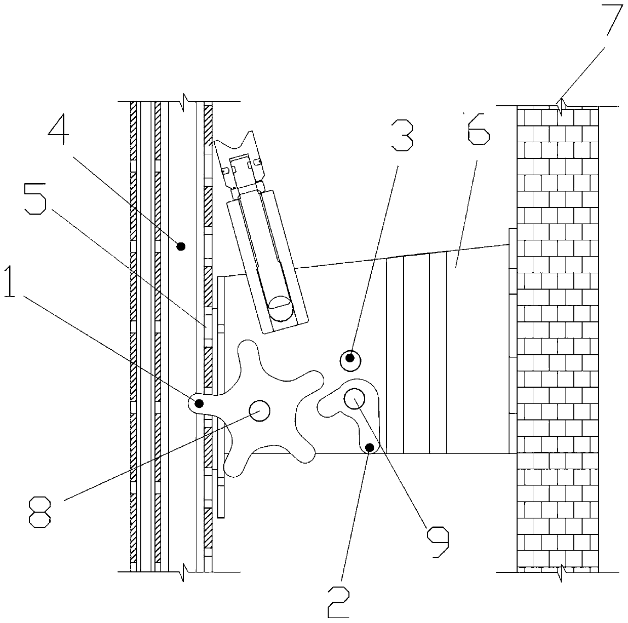
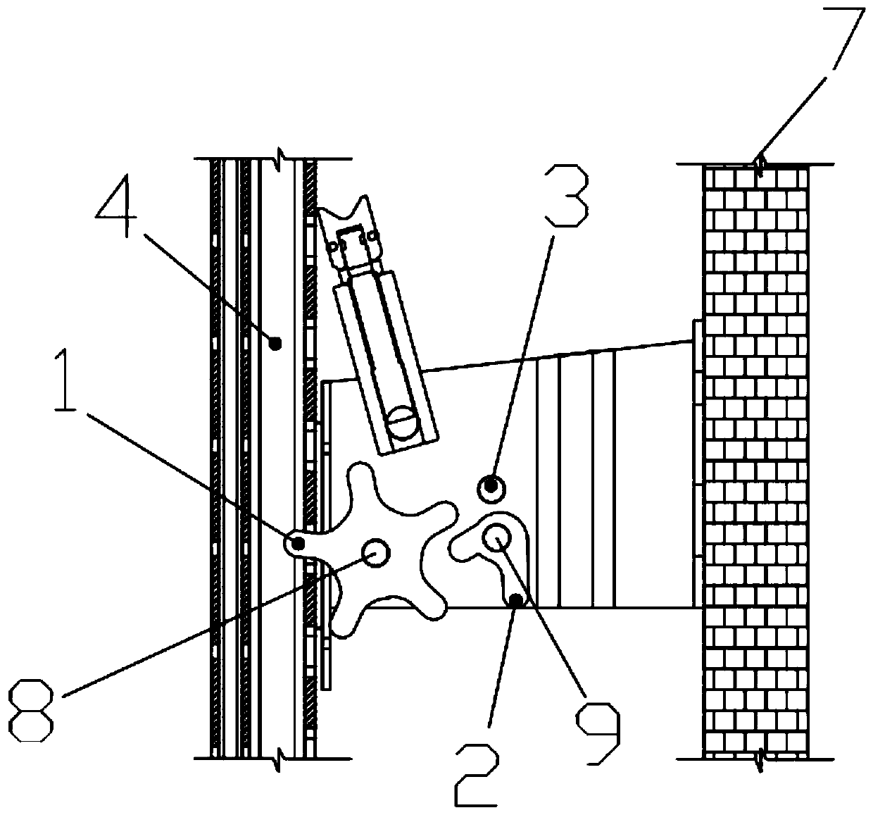
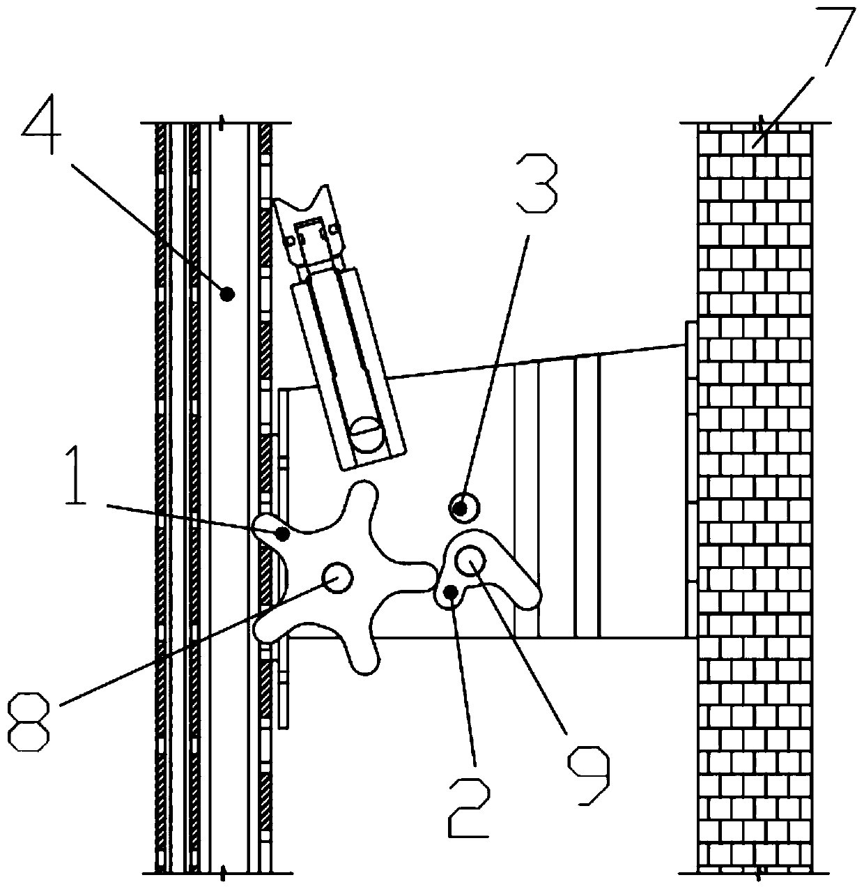
[0040] The technical solutions of the present invention will be clearly and completely described below in conjunction with the embodiments. Obviously, the described embodiments are part of the embodiments of the present invention, but not all of them. Based on the embodiments of the present invention, all other embodiments obtained by persons of ordinary skill in the art without making creative efforts belong to the protection scope of the present invention.

[0041] In describing the present invention, it is to be understood that the terms "center", "longitudinal", "transverse", "length", "width", "thickness", "upper", "lower", "front", " Back", "Left", "Right", "Straight", "Horizontal", "Top", "Bottom", "Inner", "Outer", "Clockwise", "Counterclockwise", etc. or The positional relationship is based on the orientation or positional relationship shown in the drawings, which is only for the convenience of describing the present invention and simplifying the description, rather t...


PUM


Abstract

The invention provides an over-speed stop mechanism. The over-speed stop mechanism comprises a stop road wheel, a stop ejector pin, a stop beam and a stop road wheel drive device, wherein the stop road wheel drive device and the stop ejector pin are separately arranged at the two sides of the stop road wheel; while the stop road wheel drive device moves, the stop road wheel drive device can drivethe stop road wheel to rotate, and the stop road wheel can drive the stop ejector pin to rotate; while the stop road wheel drive device moves in a first direction and moves at constant speed in a second direction, the stop ejector pin does not limit rotation of the stop road wheel; and while the stop road wheel drive device moves at speed exceeding predetermined speed in the second direction, thestop ejector pin automatically returns to a locking state. The mechanism solves potential safety hazards due to the fact that spring rust and corrosion resistance is poor and elastic fatigue is liableto occur after use throughout the year, and avoids manpower resource waste caused by daily checking and replacing a spring. Compared with spring return, the over-speed stop mechanism improves triggersensitivity. Moreover, the over-speed stop mechanism is simple, firm and reliable in structure, is strong is rust and corrosion resistance, and greatly reduces a fault rate.

Description

technical field [0001] The invention relates to the technical field of lifting scaffolding, in particular to an overspeed stop mechanism and lifting scaffolding. Background technique [0002] The attached lifting scaffold is referred to as the climbing frame, which is mainly used in high-rise buildings. It can climb up or down along the building, and turn the suspended operation into the internal operation of the frame. It is not limited by the height of the building, saving manpower and materials. Great development advantage in high-rise buildings. [0003] The climbing frame is connected to the outer wall of the building through the wall-attached support, and the electric hoist is used as the power to climb up. The anti-drop device realizes the jamming protection function in the case of an accidental fall, and is an important safety device for the attached lifting scaffold. [0004] In the current climbing frame scheme, the anti-falling device adopts spring reset. Since ...

Claims


Application Information

Patent Timeline
Patent Type & Authority Applications(China)
IPC IPC(8): E04G3/28E04G5/00E04G5/04
CPCE04G3/28E04G5/00E04G5/046
Inventor 王民杰
Owner 广西精通可立德工程科技有限公司
Why Eureka
Try Eureka