Repeatedly utilized grass grid sand fixing method

A sand-fixing method and a grass-checking technology, applied in soil protection, climate change adaptation, construction, etc., can solve problems such as unreusable, and achieve the effects of easy updating and maintenance at any time, simple method, and convenient construction.

Active Publication Date: 2014-01-29
XINJIANG INST OF ECOLOGY & GEOGRAPHY CHINESE ACAD OF SCI
View PDF7 Cites 5 Cited by
  • Summary
  • Abstract
  • Description
  • Claims
  • Application Information

AI Technical Summary

Problems solved by technology

This method solves the problem that the grass grid sand barrier cannot be reused after being buried. It can make full use of plant straw resources, save raw material pretreatment costs, enhance the anti-corrosion ability of straw, and make on-site construction easier.

Method used


Image

  • Repeatedly utilized grass grid sand fixing method
  • Repeatedly utilized grass grid sand fixing method
  • Repeatedly utilized grass grid sand fixing method

Examples


Embodiment 1

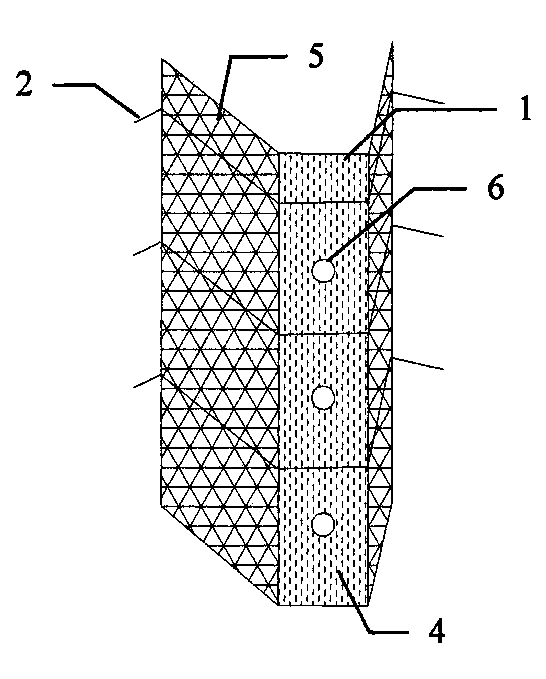
[0025] U-shaped fixer: U-shaped fixer 1 is made of a base plate 4 and two side plates 5, jacks 6 are set every 30 cm on the center of base plate 4, and U-shaped fixer 1 is 3 cm wide;

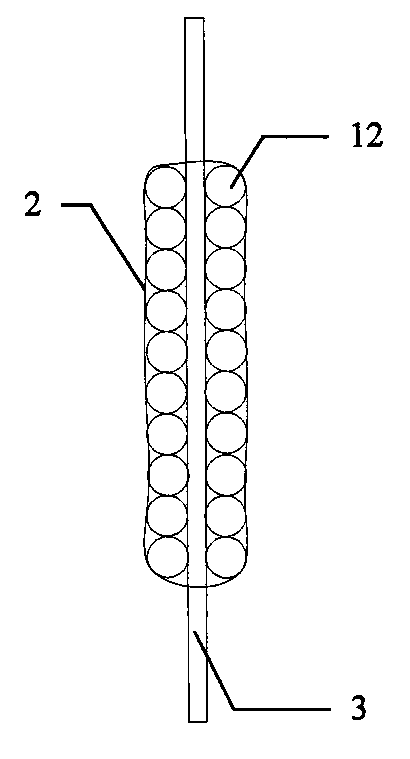
[0026] Plant straw binding: Insert the fixing braze 3 into the socket 6 on the bottom plate 4 of the U-shaped holder 1, spread the binding wire 2 on the bottom plate 4 and the side plate 5, and place a section of binding wire 2 every 10cm with a diameter of 1mm iron wire;

[0027] Put the plant straw 12 flatly in the gap between the side plate 5 and the fixed braze 3, fill the plant straw 12 with a thickness of 1 cm and a height of 5 cm, and then tighten the two ends of the iron wires of the binding wire 2 one by one to form a whole plant straw handle ;

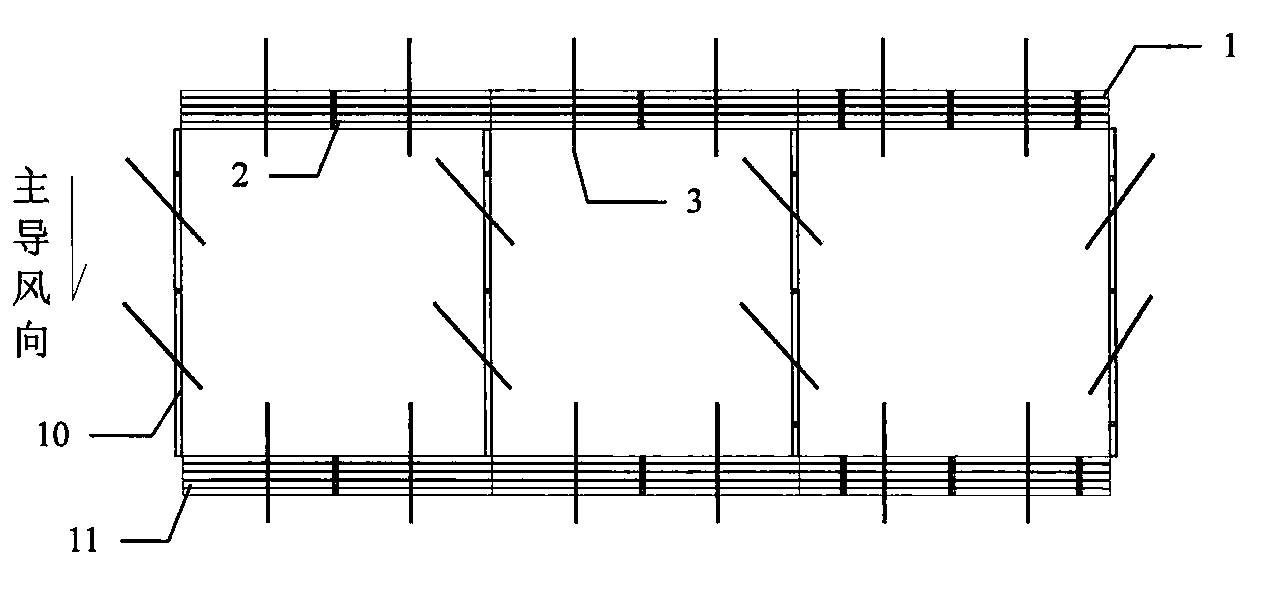
[0028] Cutting the finished whole plant straw handles into short handles 10 with a length of 1m and long handles 11 with a length of 2m, and then transporting the cut plant straw handles to the sand prevention project site;

[0029] Rake prod...

Embodiment 2

[0033] U-shaped fixer: U-shaped fixer 1 is made of a base plate 4 and two side plates 5, jacks 6 are set every 30 cm on the center of base plate 4, and U-shaped fixer 1 is 5 cm wide;

[0034] Plant straw binding: Insert the fixing braze 3 into the socket 6 on the bottom plate 4 of the U-shaped holder 1, spread the binding wire 2 on the bottom plate 4 and the side plate 5, and place a section of binding wire 2 every 15cm to resist aging nylon rope;

[0035] Put the plant straw 12 flatly in the gap between the side plate 5 and the fixed braze 3, the plant straw filling layer is 3 cm thick and 10 cm high, and then tighten the two ends of the binding wire 2 one by one to form a whole plant straw handle;

[0036] Cutting the prepared plant straw handles into short handles 10 with a length of 1m and long handles 11 with a length of 3m, and then transporting the cut plant straw handles to the sand control project site;

[0037] Rake production: fix the handle 7 on the top of the sup...

Embodiment 3

[0041] U-shaped fixer: U-shaped fixer 1 is made of a base plate 4 and two side plates 5, jacks 6 are set every 40cm on the center of base plate 4, and U-shaped fixer 1 is 10cm wide;

[0042] Plant straw binding: Insert the fixing braze 3 into the jack 6 on the bottom plate 4 of the U-shaped holder 1, spread the binding wire 2 on the bottom plate 4 and the side plate 5, and place a section of binding wire 2 every 20cm with a diameter of 2mm the iron wire;

[0043] Put the plant straw 12 flatly in the gap between the side plate 5 and the fixed braze 3, the plant straw filling layer is 5 cm thick and 20 cm high, and then tighten the two ends of the binding wire 2 one by one to form a whole plant straw handle;

[0044] The prepared plant straws are cut into short handles 10 with a length of 1m and long handles 11 with a length of 4m, and then the cut plant straws are transported to the sand control project site;

[0045] Rake production: fix the handle 7 on the top of the support...


PUM


Abstract

The invention discloses a repeatedly utilized grass grid sand fixing method. The method relates to a new grass grid sand-protecting barrier method and comprises the steps of: bundling up plant straws into grass bundles; paving the plant bundles on a sand surface to form a grid shape; fixing the plant straws on the sand surface by using a fixed drill rod; lifting the plant straws on the ground surface through a hook on a rake when lots of sands are accumulated in the square grids, wherein the anti-wind and sand-fixing capability of the grass grid sand-protecting barriers is recovered. The method is used for fixing flowing sand surfaces, can prevent hazards of sand storms of oasis cities and towns and engineering construction, can help afforestation in quicksand and can improve rate of survival of nursery stocks. The method can be widely applied to extremely droughty desert areas. If the straws are subjected to good preservative treatment, the method is also applicable to other windy and dusty areas with relatively great rainfalls. The repeatedly utilized grass grid sand fixing method solves the difficulty that the grass sand-protecting barrier after being buried in sands cannot be utilized repeatedly, is capable of saving raw material pre-treatment expense, enhancing erosion resistance of the straws and simplifying site construction besides fully utilizing the plant straw resource, and can be widely applied to the protection and treatment of hazards of sand storms in the extremely draughty desert areas.

Description

technical field [0001] The invention relates to sand prevention and sand control technology, in particular to a reusable grass grid sand fixation method. Background technique [0002] Desertification is one of the major global environmental problems at present. It directly threatens the foundation of production and development of human society, resulting in a continuous decline in land productivity. According to statistics, 3.6 billion hectares of arable land and pastures around the world are threatened by desertification, and desertification causes direct economic losses of more than 42 billion U.S. dollars every year. [0003] Numerous desertification prevention and control methods have been formed at home and abroad. According to the prevention and control principles, they can be divided into mechanical sand control, chemical sand control, and biological sand control. Among them, mechanical sand control has the advantages of low cost and quick results. Grass grid sand ba...

Claims


Application Information

Patent Timeline
Patent Type & Authority Applications(China)
IPC IPC(8): E02D3/00
CPCY02A40/22
Inventor 李生宇徐新文雷加强范敬龙王世杰
Owner XINJIANG INST OF ECOLOGY & GEOGRAPHY CHINESE ACAD OF SCI
Why Eureka
Try Eureka