
Extrusion device for drilling pressurized water slurry replacement and construction process

A extrusion device and slurry replacement technology, which is applied in mining equipment, shaft equipment, earthwork drilling and mining, etc., can solve problems such as engineering waste, and achieve the effects of convenient use, low processing cost, and convenience for next use

Pending Publication Date: 2020-08-07
SHAANXI ZHENGTONG COAL IND CO LTD
View PDF0 Cites 2 Cited by
  • Summary
  • Abstract
  • Description
  • Claims
  • Application Information

AI Technical Summary

Problems solved by technology

[0004] The purpose of the present invention is to provide an extrusion device and a construction process for drilling holes to press water to replace grouting, so as to solve the problem of engineering waste caused by the use of advancing segmental grouting in existing ground drilling grouting projects

Method used


Image

  • Extrusion device for drilling pressurized water slurry replacement and construction process
  • Extrusion device for drilling pressurized water slurry replacement and construction process
  • Extrusion device for drilling pressurized water slurry replacement and construction process

Examples


Embodiment 1

[0034] see figure 1 , figure 2 , image 3 , Figure 4 , Figure 5 , Figure 6 and Figure 7 , the present invention provides a technical solution:

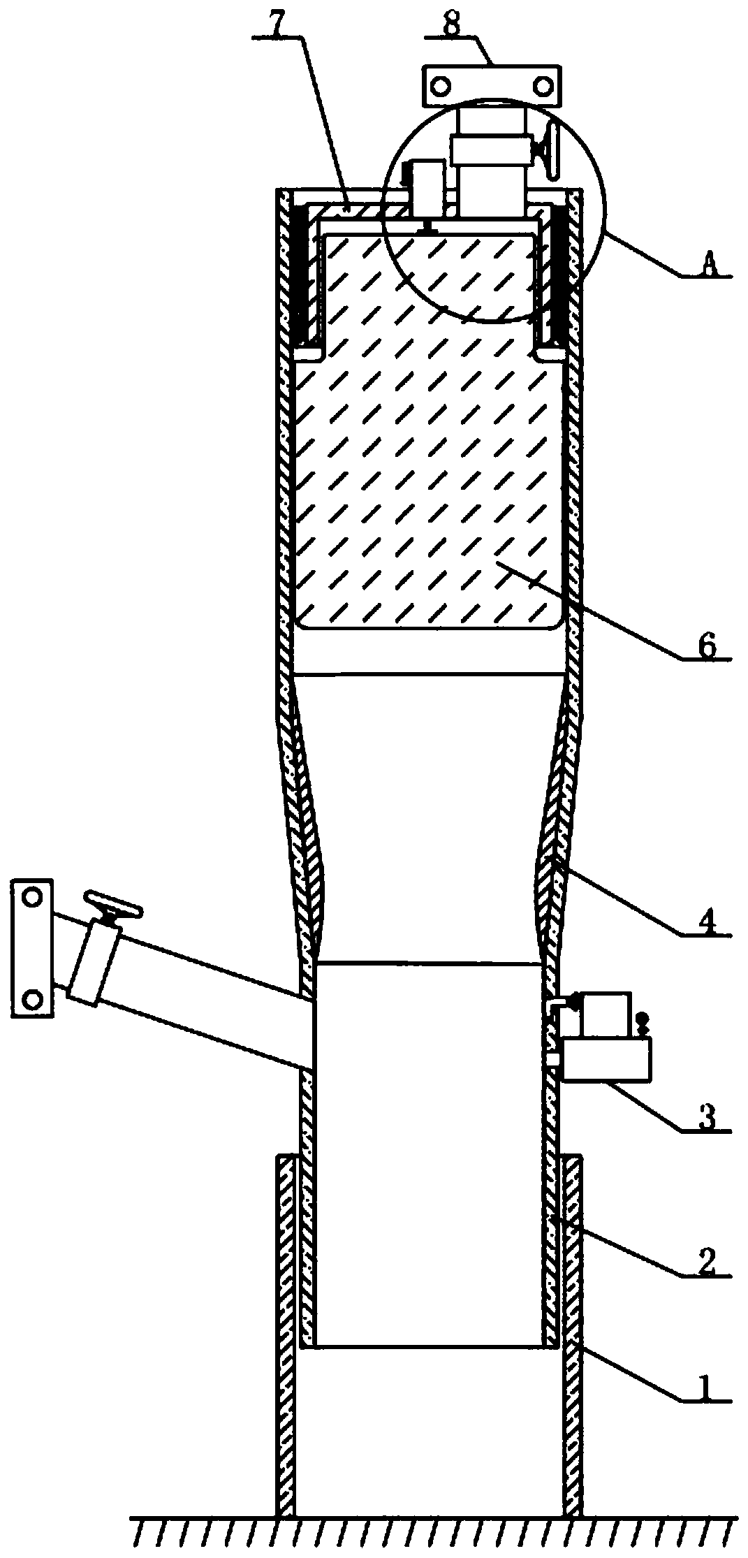
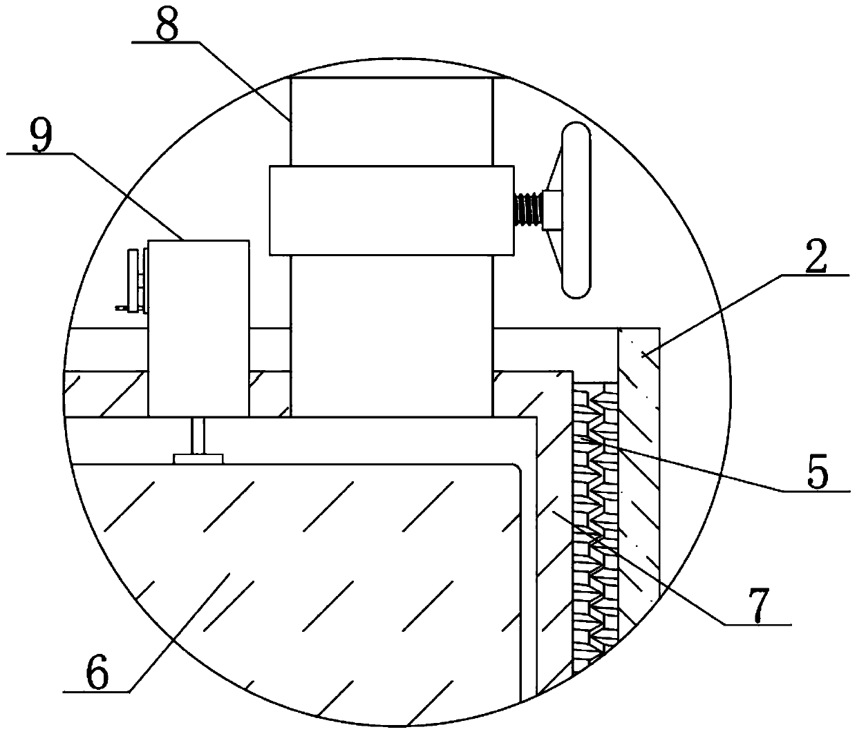
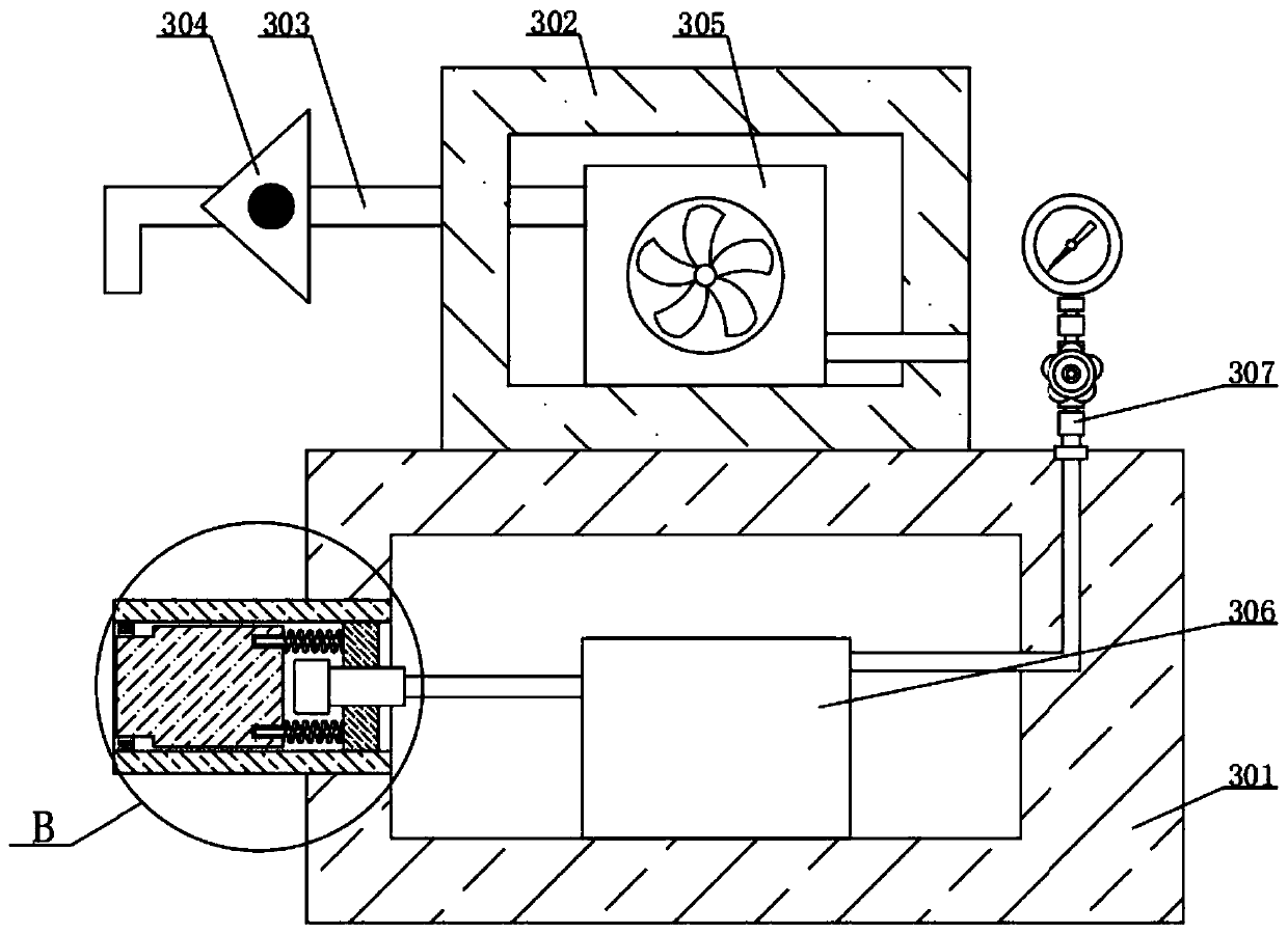
[0035]An extrusion device and construction process for drilling and pressing water to replace slurry, including a pipe 1 and a device pipe 2, the inner side of the pipe 1 is spirally connected with the device pipe 2, and the right end of the device pipe 2 is fixedly connected with the detection device 3, the detection device 3 It includes a pressure measuring box 301 and a protective box 302. The upper surface of the pressure measuring box 301 is fixedly connected with a protective box 302. The inner side of the protective box 302 is fixedly connected with a fan 305. The fan 305 can input air into the device 2 to detect its sealing performance. The left and right sides of 305 are connected with a ventilation pipe 303, the outside of the ventilation pipe 303 is fixedly connected with the protective box 302, the outside of th...

Embodiment 2

[0044] see figure 1 , figure 2 , image 3 , Figure 4 , Figure 5 , Figure 6 and Figure 7 , the present invention provides a technical solution:

[0045]An extrusion device and construction process for drilling and pressing water to replace slurry, including a pipe 1 and a device pipe 2, the inner side of the pipe 1 is spirally connected with the device pipe 2, and the right end of the device pipe 2 is fixedly connected with the detection device 3, the detection device 3 It includes a pressure measuring box 301 and a protective box 302. The upper surface of the pressure measuring box 301 is fixedly connected with a protective box 302. The inner side of the protective box 302 is fixedly connected with a fan 305. The fan 305 can input air into the device 2 to detect its sealing performance. The left and right sides of 305 are connected with a ventilation pipe 303, the outside of the ventilation pipe 303 is fixedly connected with the protective box 302, the outside of th...


PUM


Abstract

The invention relates to the technical field of drilling engineering grouting, in particular to an extrusion device for drilling pressurized water slurry replacement and a construction process. The extrusion device comprises a pipeline and a device pipe, the inner side of the pipeline is spirally connected with the device pipe, the right end face of the device pipe is fixedly connected with a detection device, a sealing frame is arranged on the inner side of the upper portion of the device pipe, threads are arranged on the outer side of the sealing frame, the sealing frame is spirally connected with the device pipe through the threads, a rubber extrusion plug is arranged on the inner side of the sealing frame, a lifting device is fixedly connected to the upper end face of the rubber extrusion plug, and a discharging device is fixedly connected to the right side of the upper end face of the sealing frame. According to the device, through the arrangement of the discharging pipe, a valve,the rubber extrusion plug and the sealing frame, the rubber extrusion plug continuously extrudes forwards, and residual cement in a horizontal section hole is continuously extruded into a stratum until reaching a target hole section; by means of the arrangement, the device is convenient to use, can solve the hole sweeping problem caused by segmented grouting in existing drilling engineering, andgreatly improves the construction efficiency and construction cost.

Description

technical field [0001] The invention relates to the technical field of drilling engineering grouting, in particular to an extrusion device and a construction process for drilling water to replace grout. Background technique [0002] The current drilling engineering grouting technology is gradually being applied to the sealing and reinforcement of strata under various geological conditions, such as geological faults, goaf fissures, primary stratum fissures, etc., and grouting is carried out after drilling holes in the target area through directional drilling technology , while the grouting in the construction of the above-mentioned projects, the ground orifice is directly connected to the grouting pump for full-hole grouting. It is necessary to pull out all the drilling tools. Before grouting, it is necessary to press water to press the mud and mud cake in the hole into the formation. After the grouting is completed, it is necessary to press water again to press out all the c...

Claims


Application Information

Patent Timeline
IPC IPC(8): E21B33/138E21D11/10E21B47/06E21B47/00E21F17/18
CPCE21B33/138E21D11/10E21B47/06E21B47/00E21F17/18
Inventor 段西亮孙亚岳王青振任邓君顾玉明邢介波梁西栋
Owner SHAANXI ZHENGTONG COAL IND CO LTD
Learn More