
Multi-level energy absorbing tube

An energy-absorbing tube, multi-level technology, applied in shock absorbers, mechanical equipment, transportation and packaging, etc., can solve problems such as unstable deformation modes, improve structural energy absorption, save manufacturing costs, and achieve high energy absorption efficiency Effect

Pending Publication Date: 2020-08-07
CENT SOUTH UNIV
View PDF0 Cites 0 Cited by
  • Summary
  • Abstract
  • Description
  • Claims
  • Application Information

AI Technical Summary

Problems solved by technology

[0004] The purpose of the present invention is to solve the problem of unstable deformation mode in the single-layer transverse sinusoidal corrugated pipe energy-absorbing structure, and to provide a multi-level energy-absorbing pipe, which plays a stabilizing role through the interaction of the inner and outer layer pipes during the deformation process. Improved deformation and better energy absorption compared to single-layer structures

Method used


Image

  • Multi-level energy absorbing tube
  • Multi-level energy absorbing tube
  • Multi-level energy absorbing tube

Examples


Embodiment 1

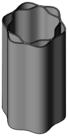
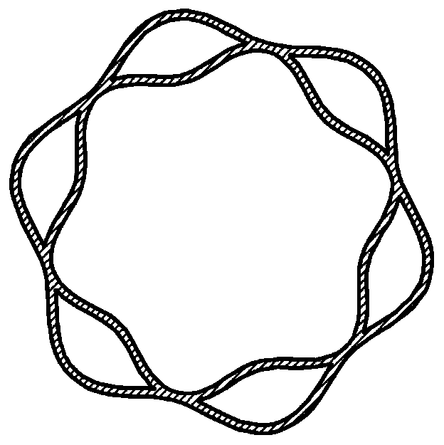
[0036] Such as Figure 2a , Figure 2b The two-layer energy absorbing tube shown (referred to as a type of energy absorbing tube in the present invention) has two sinusoidal waves spliced ​​in its cross section. The trough of the outer sinusoidal corrugation is tangent to the peak of the inner sinusoidal corrugation. A sine wave corresponding to the sine function has the same amplitude A and wave number N, and the basic nominal radius R 0 Different, in this embodiment, the basic nominal radius R of the outer tube is maintained 0 To set a value of 25mm, change the value of the basic nominal radius of the inner tube so that the trough of the sinusoidal corrugation of the section of the outer tube is tangent to the peak of the sinusoidal corrugation of the section of the inner tube. Among them, the tube length L in this embodiment is 100 mm.

Embodiment 2

[0038] Such as image 3 Shown is another type of two-layer energy absorbing tube structure (referred to as the second type of energy absorbing tube in the present invention). The crests and troughs of the two sinusoidal corrugations spliced ​​in the cross section are directly opposite, and the two sinusoidal corrugations correspond to Sine function amplitude A, ripple number N, basic nominal radius R 0 The same respectively.


PUM


Abstract

The invention discloses a multi-level energy absorbing tube, which is composed of at least two layers of pipe walls by splicing, wherein the energy absorbing tube comprises a first-level hollow pipe surrounded by inner pipe walls and a number of second-level hollow pipes formed by two adjacent layers of pipe walls by splicing, and the second-level hollow pipes are arranged around the first-level hollow pipe. In particular, the energy absorbing tube is provided with the cross section of a spliced shape of n sinusoidal corrugations, a specific structure is that the trough of the outer sinusoidalcorrugations in every two sinusoidal corrugations spliced on the cross section of the energy absorbing tube is tangent to the peak of the inner sinusoidal corrugations, and the other structure is a double-layer energy absorbing tube, having the peaks and troughs of the two sinusoidal waves spliced on the cross section directly opposite. The improved structure of the energy absorbing tube makes the interaction between the inner and outer layer tubes stable during the deformation process, improves the deformation, and enhances the energy absorption effect.

Description

Technical field [0001] The invention belongs to the technical field of automobile collisions, and specifically relates to a multi-level energy absorbing tube. Background technique [0002] Thin-walled structures are widely used due to their low cost and high energy absorption characteristics. Among them, the thin-walled round tube is one of the most widely used energy absorbing structures. When the traditional round tube is subjected to an axial impact load, it often exhibits a higher initial peak force and a larger force fluctuation range. Under the action of a larger initial peak force, a larger acceleration will be produced during the impact, which will increase the damage to the occupants. Many researchers have reduced the initial peak force by introducing corrugations in the axial direction, but at the same time it will also reduce the specific energy absorption SEA of the structure and weaken the energy absorption effect of the structure. [0003] Xiaolin Deng et al. propo...

Claims


Application Information

Patent Timeline
Patent Type & Authority Applications(China)
IPC IPC(8): F16F7/12B60R19/18B61F19/04
CPCF16F7/128B60R19/18B61F19/04F16F2236/04
Inventor 姚曙光杨紫许平彭勇鲁寨军姚松
Owner CENT SOUTH UNIV
Learn More