Externally connected straight-through phase change heat exchanging device

A phase-change heat and straight-through technology, applied to indirect heat exchangers, lighting and heating equipment, etc., can solve the problems of inconvenient transportation and loading and unloading, large volume of phase-change heat devices, blockage of water distribution, etc., to achieve convenient transportation The effects of loading and unloading, convenient cleaning and maintenance, and improved heat exchange efficiency

Pending Publication Date: 2020-08-07
HIT HARBIN INST OF TECH KINT TECH
View PDF0 Cites 0 Cited by
  • Summary
  • Abstract
  • Description
  • Claims
  • Application Information

AI Technical Summary

Problems solved by technology

[0004] The present invention aims to solve the problem that the volume of the existing phase change heat device is too large, it is not convenient to transport and load, and the problem th

Method used


Image

  • Externally connected straight-through phase change heat exchanging device
  • Externally connected straight-through phase change heat exchanging device
  • Externally connected straight-through phase change heat exchanging device

Examples


specific Embodiment approach 1

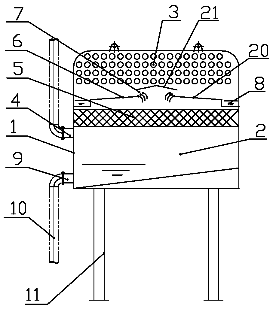
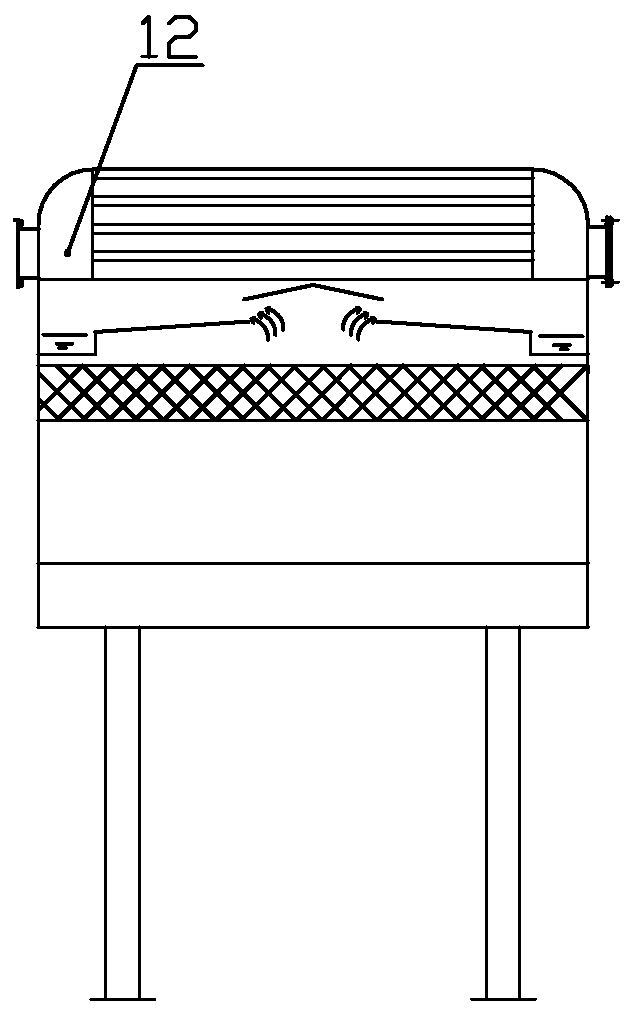
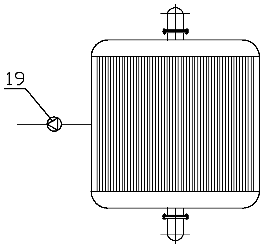
[0028] Specific implementation mode one: combine Figure 1~5 Describe this embodiment, an externally connected through-type phase-change heat device, which includes N externally connected through-type phase-change heat units, where N≥1, and each externally connected through-type phase-change heat unit It includes a casing (1) and a nozzle (4), the casing (1) is sealed and has a cavity structure inside, the casing (1) is connected with a vacuum pump (19), and the casing (19) is connected to the casing (19). The inside of the body (1) is evacuated, and the upper part of the cavity structure is arranged with a heat exchange tube bundle (3), and the lower part of the cavity structure forms a flash chamber (2) through the action of the vacuum pump (19) and the heat exchange tube bundle (3), Nozzle (4) is arranged in communication with the upper side wall of the flash chamber (2), and the liquid to be flashed enters the flash chamber (2) through the nozzle (4) for flashing, and the ...

specific Embodiment approach 2

[0051] Specific implementation mode two: as Figure 1~5 As shown, the heat exchange tube bundle (3) in each effect includes several parallel heat exchange straight tubes, and the several heat exchange straight tubes are laid horizontally on the upper part of the cavity structure.

specific Embodiment approach 3

[0052] Specific implementation mode three: as Figure 1~5 As shown, the heat exchange tube bundle (3) in each effect includes at least one layer of heat exchange tube layers, and each layer of heat exchange tube layers includes heat exchange elbows arranged coaxially and horizontally sequentially from inside to outside. (Each heat exchange elbow has a ring structure.)


PUM


Abstract

The invention discloses an externally connected straight-through phase change heat exchanging device, and belongs to the field of energy technologies. The problems that an existing phase change heat exchanging device is too large in size and inconvenient to transport, load and unload, and a liquid inlet mode and water distribution mode of an existing flash evaporator are prone to causing blockingare solved. The externally connected straight-through phase change heat exchanging device comprises N externally connected straight-through phase change heat exchanging single bodies, wherein N is greater than or equal to 1. Each externally connected straight-through phase change heat exchanging single body comprises a shell and a nozzle. Each shell is sealed and has a cavity structure inside. Each shell communicates with a vacuum pump. The inside of each shell is evacuated by the vacuum pump. The upper part of each cavity structure is provided with a heat exchange tube bundle, and the lower part of each cavity structure forms a flash chamber. Each nozzle communicates with the upper side wall of the corresponding flash chamber. Liquid to be flashed enters the flash chambers through the nozzles for flashing, steam obtained after flashing moves upward to the upper parts of the cavity structures and exchanges heat with liquid to be heated in the heat exchange tube bundles, so that the temperature of the liquid to be heated in the heat exchange tube bundles rises.

Description

technical field [0001] The invention relates to an externally connected through-type phase-change heat device, which belongs to the technical field of energy and environmental protection. Background technique [0002] A phase-change heat device in the prior art generally includes: a flash evaporator, a condenser, a vacuum system, a control system and some connecting pipelines. The principle of the phase conversion heat device is to use the principle of flashing low-temperature waste hot water under vacuum conditions, and the generated flash steam enters the condenser to heat the heating circulating water, and then the heating circulating water heats the surrounding buildings. Its basic function is to flash low-temperature water, and the use of flash steam heat is suitable for heating; in addition, the use of flash to concentrate industrial wastewater can achieve the effect of reducing industrial wastewater. [0003] In the phase-change heat device in the prior art, the flas...

Claims


Application Information

Patent Timeline
IPC IPC(8): F28D15/02
CPCF28D15/0266
Inventor 李金峰宋乃秋李伟张勇尚德敏黄伟成
Owner HIT HARBIN INST OF TECH KINT TECH
Why Eureka
Try Eureka