Device and method for testing delay index of observing and aiming equipment

A technology of equipment and indicators, applied in the direction of testing optical performance, etc., can solve problems such as unintuitiveness and cumbersome testing process, and achieve the effect of facilitating processing and storage, fast testing speed, and strong versatility

Pending Publication Date: 2020-08-07
江苏北方湖光光电有限公司
View PDF0 Cites 0 Cited by
  • Summary
  • Abstract
  • Description
  • Claims
  • Application Information

AI Technical Summary

Problems solved by technology

[0004] The purpose of the present invention is to provide a device and method for testing the delay index of sighting and sighting equipment, so as to solve the existing equipment that requires high real-time performance. Generally, the detectors and circuits in the equipment are tested by waveforms. Its time characteristics require disassembly and testing, and the testing process is cumbersome and unintuitive.

Method used


Image

  • Device and method for testing delay index of observing and aiming equipment
  • Device and method for testing delay index of observing and aiming equipment

Examples


Embodiment 1

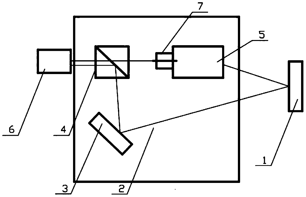
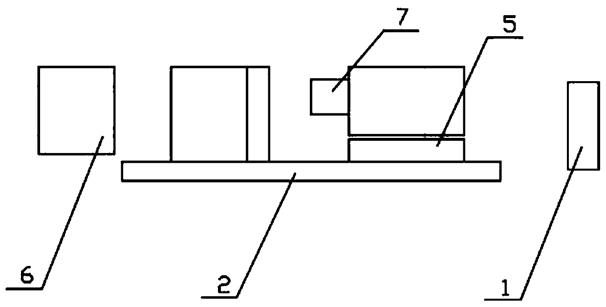
[0023] The invention provides a device for testing the delay index of sighting and sighting equipment, the structure of which is as follows: figure 1 and figure 2 shown. It includes a base 2, a millisecond meter 1, a plane mirror 3, a combined prism 4 and a camera 6, wherein the base 2 is used to fix the equipment under test 7; the millisecond meter 1 is placed on one side of the base 2; the The plane reflector 3 is movably arranged on the base 2; the combined prism 4 is arranged at the front end of the eyepiece of the equipment under test 7; the camera 6 is placed on one side of the base 2, and is connected to the The combined prism 4 and the eyepiece of the device under test 7 are located on a straight line. Preferably, the camera 6 is a high-speed camera capable of taking pictures in a short time.

[0024] Specifically, a bracket 5 is provided on the base 2 for fixing the equipment under test 7 . The combined prism 4 includes two right-angle prisms, and the glued surfa...


PUM


Abstract

The invention discloses a device and a method for testing a delay index of observing and aiming equipment, and belongs to the technical field of photoelectric testing. The device for testing the delayindex of the observing and aiming equipment comprises a base, a millisecond meter, a plane mirror, a combined prism and a camera. The base is used for fixing tested equipment. A millisecond meter isarranged on one side of the base. The plane mirror is movably arranged on the base. The combined prism is arranged at the front end of an eyepiece of the tested equipment. The camera is placed on oneside of the base, and the camera, the combined prism and an ocular lens of the measured equipment are located on the same straight line. According to the device and method for testing the time delay index of the observing and aiming equipment, the testing speed is high, the tested equipment does not need to specially design a testing interface, the whole machine does not need to be disassembled, testing data is in the same picture, testing is visual, and processing and storage are facilitated. The device has good universality, and positioning and installation can be carried out according to different tested equipment. Only the support needs to be improved, and infrared equipment, low-illumination CMOS equipment, head-mounted display equipment and the like can be tested.

Description

technical field [0001] The invention relates to the technical field of photoelectric testing, in particular to a device and method for testing the delay index of sighting and sighting equipment. Background technique [0002] With the development of various photoelectric detection technologies, traditional direct-view optical systems can no longer meet the detection needs of various environments, such as infrared detection technology, low-light CMOS technology, etc., have been widely used in photoelectric detection fields such as sights and night vision goggles. . This type of equipment inevitably brings an indicator different from the traditional direct-view optical system, that is, video delay, which refers to the delay caused by the photoelectric conversion and transmission of the target light through the detector and the electro-optical conversion of the display. [0003] For some equipment that requires high real-time performance, it is necessary to control the video de...

Claims


Application Information

Patent Timeline
Patent Type & Authority Applications(China)
IPC IPC(8): G01M11/02
CPCG01M11/02
Inventor 杨海金郝芳朱佳丽邱卫根王敬梅卞臻臻陆俊青王瑶
Owner 江苏北方湖光光电有限公司
Why Eureka
Try Eureka