
A comprehensive ranging traveling wave analysis and optimization system and method

An optimization method and traveling wave technology, applied in information technology support systems, measuring electricity, measuring devices, etc., can solve problems such as failure to successfully analyze fault recording files, poor user experience, and data call freezes, etc. The effect of customer experience fluency, improving display speed, and avoiding parsing errors

Active Publication Date: 2022-04-15
CHINA SOUTHERN POWER GRID COMPANY
View PDF0 Cites 0 Cited by
  • Summary
  • Abstract
  • Description
  • Claims
  • Application Information

AI Technical Summary

Problems solved by technology

[0007] ① For fault recording data with a large amount of data, it is often impossible to successfully analyze the fault recording file due to the limitation of the storage capacity of the client;
[0008] ②Due to the large amount of data, the amount of calculation required for the data request invoked by the user is often relatively large, and there may be a lag in the data invoke process, and the user experience is poor

Method used


Image

  • A comprehensive ranging traveling wave analysis and optimization system and method
  • A comprehensive ranging traveling wave analysis and optimization system and method
  • A comprehensive ranging traveling wave analysis and optimization system and method

Examples


Embodiment 1

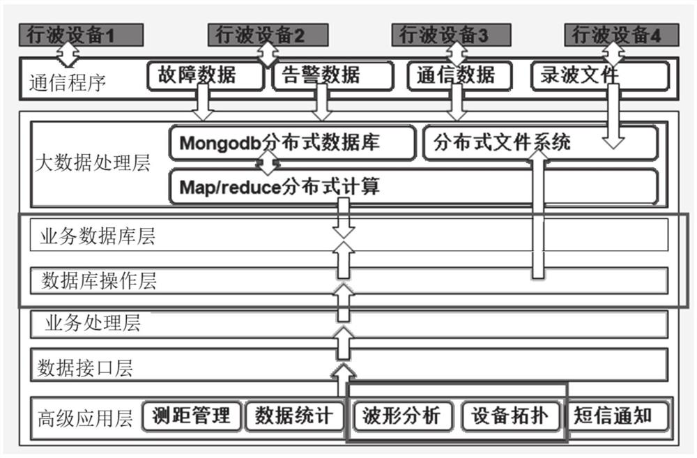
[0034] In one or more embodiments, a comprehensive ranging traveling wave analysis and optimization system is disclosed, referring to figure 1 ,include:

[0035] The data collection terminal is configured to collect transmission line fault data, and transmit the collected data to the ranging monitoring center through the communication network;

[0036] The ranging monitoring center is configured to analyze the fault waveform according to the received fault data, calculate the fault location, and save the result to a real-time database;

[0037] The communication server obtains the latest data such as fault briefing, fault waveform, and fault recording data files through the communication program according to the agreed communication protocol.

[0038] The ranging monitoring center obtains corresponding wave recording data files from the data acquisition terminal, including: fault briefing, fault waveform, fault recording data, etc. Then extract effective information from the...

Embodiment 2

[0071] In one or more embodiments, a comprehensive ranging traveling wave analysis and optimization method is disclosed, including:

[0072] Obtain the fault recording data collected by the data acquisition terminal;

[0073] According to the received fault data, the head time of the first wave is obtained, and the absolute time difference of the traveling wave transient component at both ends of the line is calculated, and the fault location of the system is obtained by calculating the fault distance and comparing it with the preset judgment standard;

[0074] Save the obtained analysis data in the database server;

[0075] When receiving the waveform analysis data request from the front-end interface, the requested analysis data is analyzed and compressed, and then sent to the front-end interface for display.


PUM


Abstract

The invention discloses a system and method for comprehensive distance measurement traveling wave analysis and optimization, comprising: a data collection terminal configured to collect transmission line fault data, and transmit the collected data to a distance measurement monitoring center through a communication network; The monitoring center is configured to analyze the fault waveform according to the received fault data, calculate the fault location, and save the result to a real-time database; wherein, the ranging monitoring center obtains the first wave head time according to the received fault data , calculate the absolute time difference of the traveling wave transient components at both ends of the line, calculate the fault distance, and compare it with the preset judgment standard to obtain the fault location of the system. The invention can effectively improve the smoothness of customer experience, and realize the comfortable, natural and smooth user experience effect of the main station of the traveling wave ranging system.

Description

technical field [0001] The invention relates to the technical field of traveling wave analysis, in particular to a comprehensive ranging traveling wave analysis and optimization system and method. Background technique [0002] The statements in this section merely provide background information related to the present invention and do not necessarily constitute prior art. [0003] With the continuous extension and expansion of the power supply network and the rapid growth of power supply, the grid structure is more reasonable and more complex. At present, the traveling wave distance measurement project provides users with efficient and rich experience with a fast, powerful, rich and customizable human-machine interface; and provides stable and durable fault data, calculation steps, and fault file storage functions to quickly troubleshoot on-site , Effectively improve the power grid operation efficiency and equipment management level. [0004] Its fault location devices are ...

Claims


Application Information

Patent Timeline
Patent Type & Authority Patents(China)
IPC IPC(8): G01R31/08
CPCG01R31/086G01R31/088Y04S10/52
Inventor 丁晓兵徐海峰史泽兵张弛范作程赵传刚郑茂然高宏慧李正红陈朝晖张静伟万信书
Owner CHINA SOUTHERN POWER GRID COMPANY
Learn More