Supercharge Your Innovation With Domain-Expert AI Agents!

Non-coherent electromagnetic detection external field automatic calibration system and method

A non-coherent, calibration technology, applied in the field of electromagnetic detection, can solve problems such as unsatisfactory application effect, inability to achieve full-link calibration of the detection system, affecting calibration efficiency and measurement accuracy, etc. The efficiency of school work, the accuracy of calibration data, and the real effect of calibration data

Active Publication Date: 2020-08-07
中国航天系统科学与工程研究院
View PDF14 Cites 0 Cited by
  • Summary
  • Abstract
  • Description
  • Claims
  • Application Information

AI Technical Summary

Problems solved by technology

There are many defects in this calibration method: first, because the calibration signal does not pass through the detection antenna, it is fed from the radio frequency front end of the detection system through a wired method, and the full link calibration of the detection system cannot be realized; The calibration signal is generated from the internal circuit of the detection system itself. The frequency coverage of the calibration signal, the complexity of the signal system, and the accuracy of the signal output are difficult to meet the calibration requirements for fully testing the function and performance of the detection system.
Another common calibration method is to use a high-precision signal instrument to feed the calibration signal from the RF front-end of the detection system, which can generate a wide-band, high-precision signal that meets the calibration requirements, but still fails to achieve full-link Calibration requirements, and when it is necessary to fully inspect each channel of the detection system, it is necessary to manually perform a large number of line change operations, which affects calibration efficiency and measurement accuracy
In addition, the above two methods are in-field calibration methods, which fail to consider the impact of external environmental factors on the detection system, and the application effect after calibration is not ideal.

Method used


Image

  • Non-coherent electromagnetic detection external field automatic calibration system and method
  • Non-coherent electromagnetic detection external field automatic calibration system and method
  • Non-coherent electromagnetic detection external field automatic calibration system and method

Examples


Embodiment Construction

[0049] The present invention will be further explained and illustrated below in conjunction with the accompanying drawings and specific embodiments.

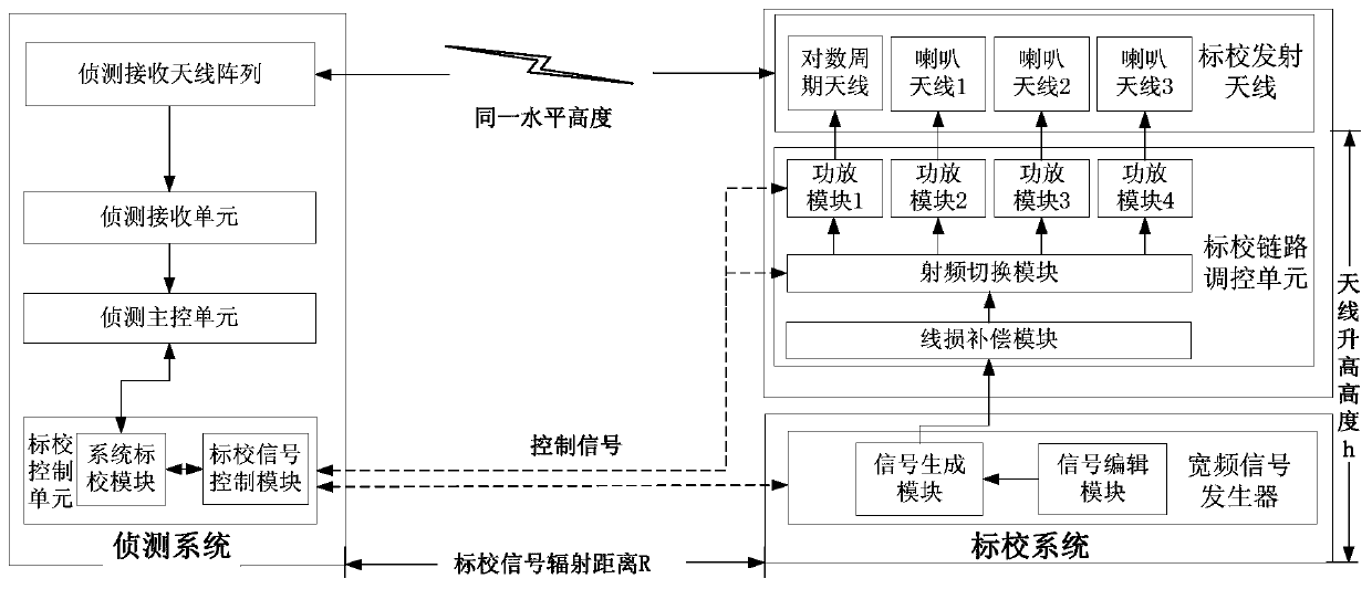
[0050] Such as figure 1 , a non-coherent electromagnetic detection field automatic calibration system, comprising a broadband signal generator, a calibration link control unit, a calibration transmitting antenna group and a calibration control unit;

[0051] A broadband signal generator, used to generate calibration signals of various frequency bands and types, and output them to the calibration link control unit;

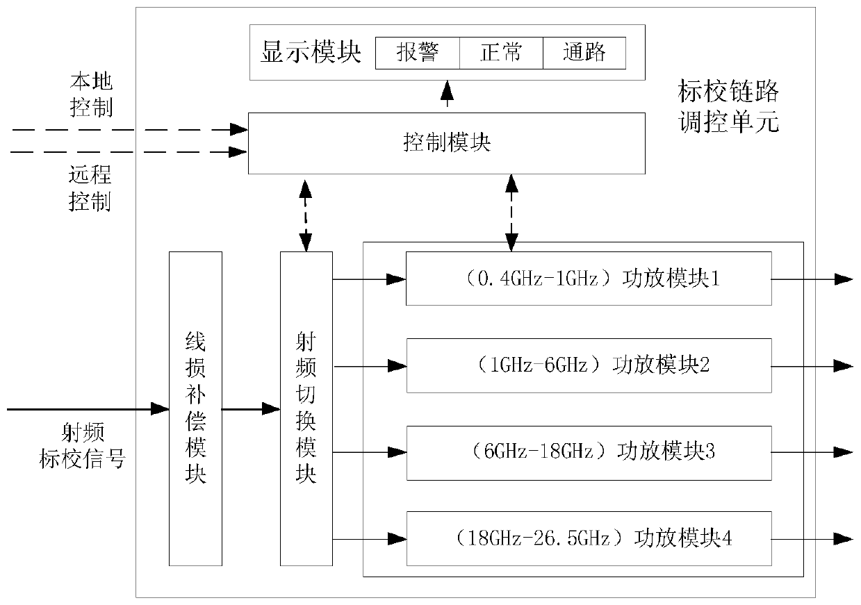
[0052] The calibration link control unit receives the calibration signal, performs power compensation, and performs power amplification according to the frequency band of the calibration signal; after the calibration signal is amplified to a fixed power value, it is output to the calibration transmitting antenna group;

[0053] The calibration transmitting antenna group receives the calibration signal amplified by t...


PUM


Abstract

The invention discloses a non-coherent electromagnetic detection external field automatic calibration system and method, and belongs to the technical field of electromagnetic detection. The system comprises a broadband signal generator, a calibration link regulation and control unit, a calibration transmitting antenna group and a calibration control unit. According to the system and method of theinvention, a non-coherent calibration mode is adopted; a calibration signal source independent of a detection system is designed; calibration transmitting antennas remotely and horizontally radiate signals towards detection antennas in an aligned and directed manner; calibration signals are fed in from the starting end of the link of the detection system in a wireless mode, so that the problem that full-link calibration of the detection system cannot be achieved through a traditional coherent calibration mode is effectively solved; and calibration data obtained through the non-coherent calibration method for simulating the actual working mode of the detection system are more real and reliable.

Description

technical field [0001] The invention relates to a non-coherent electromagnetic detection external field automatic calibration system and method, belonging to the technical field of electromagnetic detection. Background technique [0002] After the electromagnetic detection system is used for a long time, the measurement accuracy of the system will drift, which will affect the accuracy of the measurement data. If the system is not calibrated in time, the measurement data will be invalid in severe cases, which will lead to the failure of the detection task. In addition, before performing the detection task, it is necessary to test the function and performance of the detection system to fully understand and grasp the working status of the detection system to ensure that it can perform detection tasks normally. At present, a traditional calibration method is to generate a simple coherent calibration signal inside the detection system, and feed it from the RF front end of the det...

Claims


Application Information

Patent Timeline
Patent Type & Authority Applications(China)
IPC IPC(8): G01R35/00G01R29/08
CPCG01R35/005G01R29/08Y02D30/70
Inventor 李成娟吴洋徐春云张研任志国孙黎明张乐黎雨楠
Owner 中国航天系统科学与工程研究院
Features
  • R&D
  • Intellectual Property
  • Life Sciences
  • Materials
  • Tech Scout
  • Unparalleled Data Quality
  • Higher Quality Content
  • 60% Fewer Hallucinations
Learn More