Reaction chamber and etching method thereof

A reaction chamber and cavity technology, applied in discharge tubes, electrical components, circuits, etc., can solve the problems of affecting the etching accuracy, slow gas flow rate, difficult etching effect, etc., so as to improve the etching effect and improve the uniformity sexual effect

Active Publication Date: 2020-08-07
BEIJING NAURA MICROELECTRONICS EQUIP CO LTD
View PDF15 Cites 0 Cited by
  • Summary
  • Abstract
  • Description
  • Claims
  • Application Information

AI Technical Summary

Problems solved by technology

However, the traditional Bosch process is difficult to achieve the desired etching effect. For example, in the traditional Bosch process equipment, the main cylinder and the secondary cylinder are usually used to etch the central area and edge area of ​​the wafer respectively. However, with the process steps When the plasma distribution in one area changes, if the plasma distribution in the other area is not properly adjusted, it will be difficult to ensure the uniformity of the overall etching of the wafer.
Moreover, in the traditional Bosch process, there will be a phenomenon of plasma extinction in the auxiliary cylinder, which will lead to deviations between the etched shape and the target shape, seriously affecting the accuracy of etching
figure 1 It is a schematic diagram of the flow direction of reaction gas in an existing reaction chamber, such as figure 1 As shown, most of the reaction gas entering the auxiliary cylinder 11 flows toward the position away from the side wall, and a small part flows toward the position A1 close to the side wall, resulting in a low gas density at position A1 and a slow gas flow rate
Between the deposition step and the etching step, the original reactive gas will be replaced with a new reactive gas. However, the slow flow rate of the gas at position A1 will cause the original gas to remain there, and the original gas The uncertainty of the mixing ratio with the new gas makes the impedance at position A1 unstable, which in turn causes the secondary coil 12 to start and stop repeatedly under the control of the power protection device
The repeated start and stop of the auxiliary coil 12 may cause the plasma extinction phenomenon, which will lead to deviations between the etched shape and the target shape

Method used


Image

  • Reaction chamber and etching method thereof
  • Reaction chamber and etching method thereof
  • Reaction chamber and etching method thereof

Examples


Embodiment Construction

[0034] Specific embodiments of the present invention will be described in detail below in conjunction with the accompanying drawings. It should be understood that the specific embodiments described here are only used to illustrate and explain the present invention, and are not intended to limit the present invention.

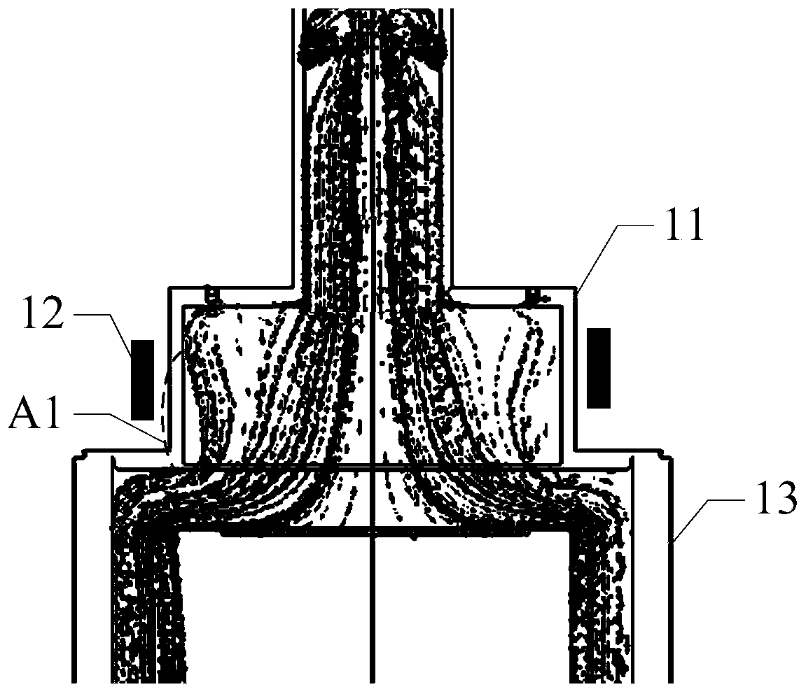
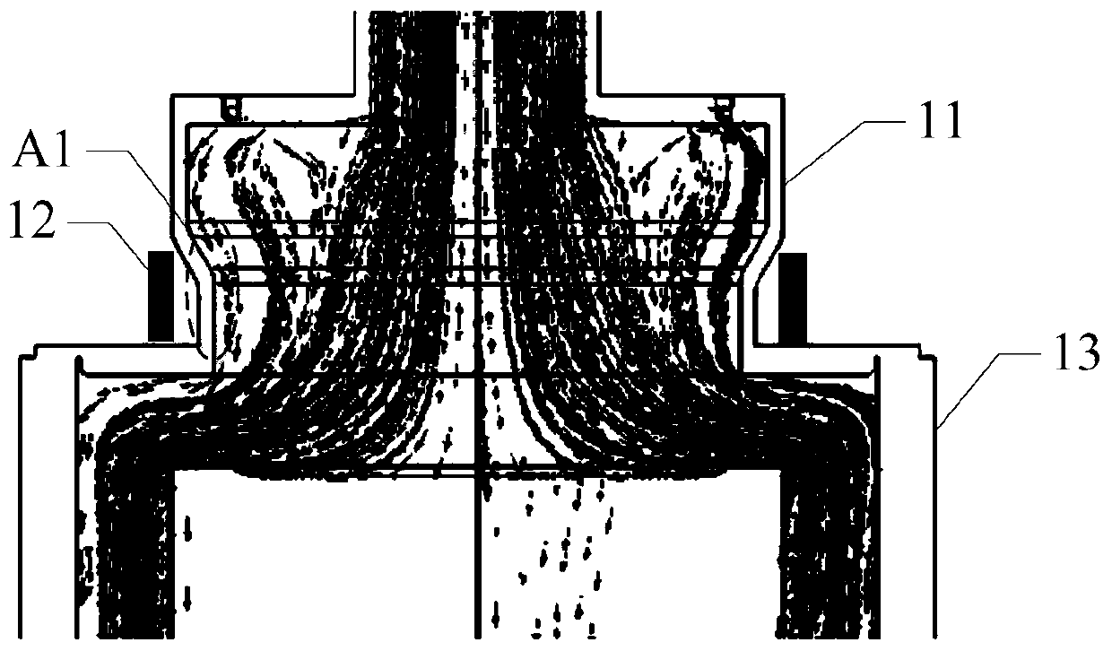
[0035] At present, in order to prevent the phenomenon of plasma extinction, the auxiliary cylinder can be set in a structure with a wide top and a narrow bottom. figure 2 It is a schematic diagram of the flow direction of reaction gas in another existing reaction chamber, such as figure 2 As shown, the size of the bottom of the auxiliary cylinder 11 is smaller than the size of the top of the auxiliary cylinder 11, the reaction gas at position A1 flows close to the side wall, the gas density is the same as that of other positions, and the gas flow rate is uniform. Between the deposition step and the etching step, Gas residue at the position A1 can be avoided, ...


PUM


Abstract

The invention provides a reaction chamber. The reaction chamber comprises a chamber body,a main cylinder, a main coil, an auxiliary cylinder, an auxiliary coil and at least one lifting structure, wherein the main cylinder is located at the top of the cavity, and the main coil is arranged around the main cylinder; the auxiliary cylinder is located between the cavity and the main cylinder, and the auxiliary coil is arranged around the auxiliary cylinder; and the at least one lifting structure is connected with the main coil or the auxiliary coil and is used for driving the main coil or the auxiliarycoil to lift along with the change of the process steps. The main coil or the auxiliary coil can be driven to ascend and descend along with changes of process steps through the lifting structure,plasma distribution on the surface of the workpiece to be machined can be adjusted easily, and therefore etching uniformity is improved. Moreover, between the deposition step and the etching step, thereaction chamber provided by the embodiment of the invention can also utilize the lifting structure to drive the auxiliary coil to be located in an area with stable impedance, so that the extinctionphenomenon of plasmas is avoided, and the etching effect is improved. The invention further provides an etching method applied to the reaction chamber, and the etching effect can also be improved.

Description

technical field [0001] The invention relates to the technical field of semiconductor processing, in particular to a reaction chamber and an etching method thereof. Background technique [0002] With the rapid development of semiconductor manufacturing technology, the use of plasma to etch the workpiece to be processed has been widely used. Taking the etching of a wafer as an example, a traditional reaction chamber includes a cavity provided with a wafer, a main cylinder located above the cavity, a secondary cylinder located between the main cylinder and the cavity, and a main coil surrounding the main cylinder and a surrounding coil. Both the main and auxiliary coils of the auxiliary cylinder are used to form an electromagnetic field, so that the reaction gas in the main and auxiliary cylinders is excited into a plasma state, and then reacts with the wafer surface to etch the wafer. [0003] At present, when etching a wafer, a Bosch (Bosch) process can be used. The Bosch pr...

Claims


Application Information

Patent Timeline
Patent Type & Authority Applications(China)
IPC IPC(8): H01J37/02H01J37/305H01J37/32
CPCH01J37/3053H01J37/023H01J37/32568
Inventor 简师节
Owner BEIJING NAURA MICROELECTRONICS EQUIP CO LTD
Why Eureka
Try Eureka