Spray pipe mounting assembly and etching device

A technology for installing components and etching devices, used in electrical components, semiconductor/solid-state device manufacturing, circuits, etc., can solve the problems of insufficient etching, excessive etching, etc., and achieve the effect of speeding up etching and avoiding short circuits between lines

Inactive Publication Date: 2020-08-07
江西卓讯微电子有限公司
View PDF15 Cites 0 Cited by
  • Summary
  • Abstract
  • Description
  • Claims
  • Application Information

AI Technical Summary

Problems solved by technology

[0004] Based on this, it is necessary to provide a nozzle installation assembly and an etching device for the problem of insufficient or excessive etching due to the over-thickness or over-thinness of the protective film during etching.

Method used


Image

  • Spray pipe mounting assembly and etching device
  • Spray pipe mounting assembly and etching device
  • Spray pipe mounting assembly and etching device

Examples


Embodiment Construction

[0025] In order to make the above objects, features and advantages of the present invention more comprehensible, specific implementations of the present invention will be described in detail below in conjunction with the accompanying drawings. In the following description, numerous specific details are set forth in order to provide a thorough understanding of the present invention. However, the present invention can be implemented in many other ways different from those described here, and those skilled in the art can make similar improvements without departing from the connotation of the present invention, so the present invention is not limited by the specific implementations disclosed below.

[0026] It should be noted that when an element is referred to as being “fixed” to another element, it can be directly on the other element or there can also be an intervening element. When an element is referred to as being "connected to" another element, it can be directly connected ...


PUM


Abstract

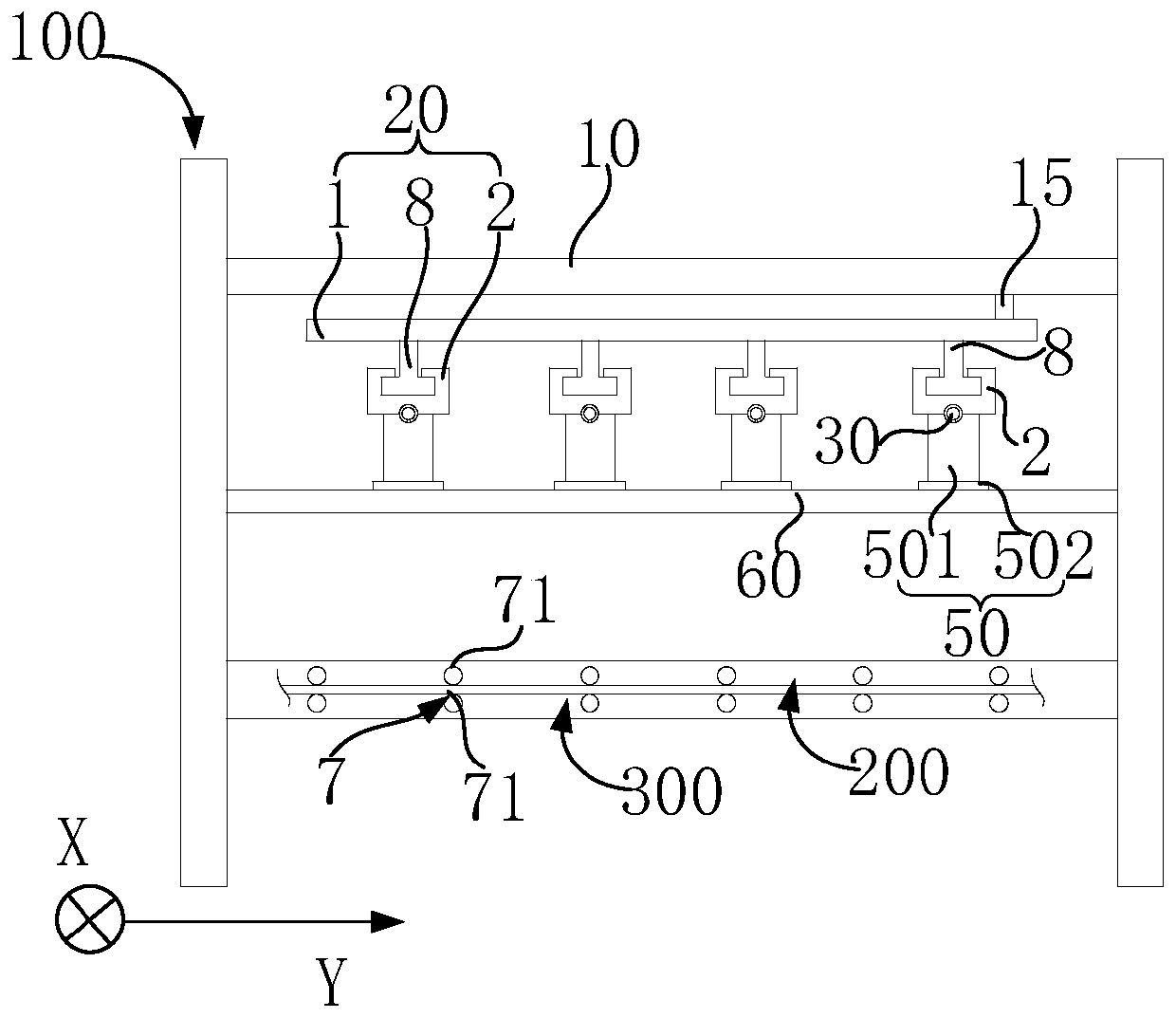
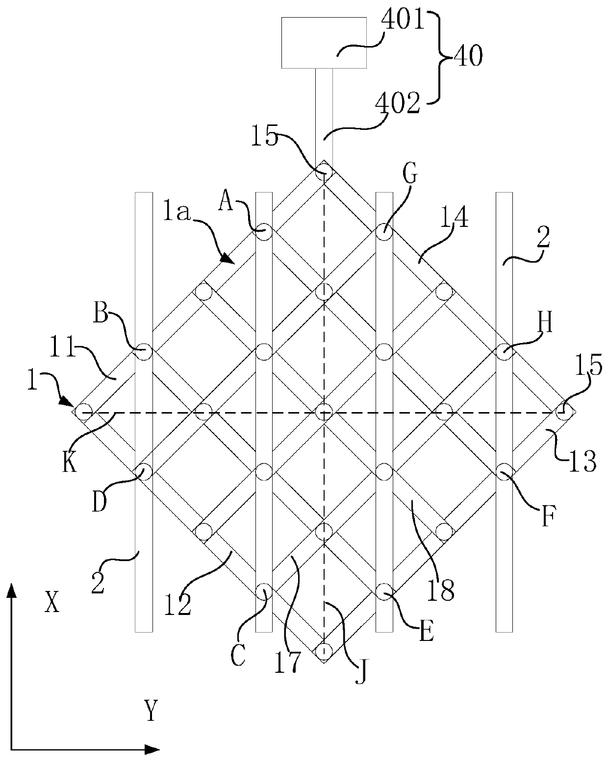
The invention relates to a spray pipe mounting assembly and an etching device. The spray pipe mounting assembly comprises a telescopic frame, sliding rails used for installing spraying pipes, the number of the sliding rails is larger than one, the sliding rails are arranged on the telescopic frame at intervals, and the telescopic frame can drive the sliding rails to move when stretching out and drawing back so as to adjust the distance between every two adjacent sliding rails, and then the distance between the spraying pipes installed on the sliding rails can be adjusted. When the spray pipe mounting assembly provided by the invention is used by the etching device, the distance between the spray pipes can be adjusted according to the actual condition of a circuit board, so that the problemof excessive or insufficient etching is avoided.

Description

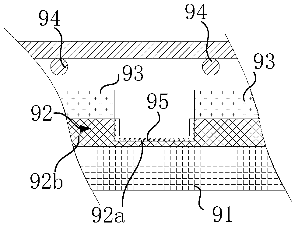
technical field [0001] The invention relates to the technical field of etching, in particular to a nozzle mounting assembly and an etching device. Background technique [0002] The copper lines on the circuit board are mainly obtained through the yellow light process, such as figure 1 As shown, during production, a layer of copper layer 92 is first provided on the substrate 91, and then a dry film 93 is provided on the surface of the copper layer 92 away from the substrate 91, and then the dry film 92 is exposed and developed to form on the dry film 92. Corresponding circuit patterns, and then expose the to-be-etched region 92a of the copper layer 92, then spray etching solution to the copper layer 92 through a plurality of nozzles 94 of the etching device to perform chemical etching, and finally peel off the dry film 93 to obtain the copper circuit 92b . In actual production, the circuit board is usually positioned under the nozzle 94 of the etching device, so that the co...

Claims


Application Information

Patent Timeline
Patent Type & Authority Applications(China)
IPC IPC(8): H01L21/67
CPCH01L21/6708
Inventor 程志政
Owner 江西卓讯微电子有限公司
Why Eureka
Try Eureka