Flow field self-adaptive battery plate structure and fuel cell

A battery plate, fuel cell technology, applied in fuel cells, circuits, electrical components, etc., can solve the problems of difficulty in verifying flow field performance, complex flow field structure, and poor practicability. The effect of uniform distribution and improved distribution uniformity

Active Publication Date: 2020-08-07
SHANGHAI JIAO TONG UNIV +2
View PDF4 Cites 7 Cited by
  • Summary
  • Abstract
  • Description
  • Claims
  • Application Information

AI Technical Summary

Problems solved by technology

However, the structure of the flow field of this invention is complex, the implementability is not strong, and the performance effect of the flow field is difficult to prove
[0007] It can be seen that there are still many problems in the design of the dual-functional flow field structure for power generation / electrolysis of URFC, and there are few related designs

Method used


Image

  • Flow field self-adaptive battery plate structure and fuel cell
  • Flow field self-adaptive battery plate structure and fuel cell
  • Flow field self-adaptive battery plate structure and fuel cell

Examples


Embodiment 1

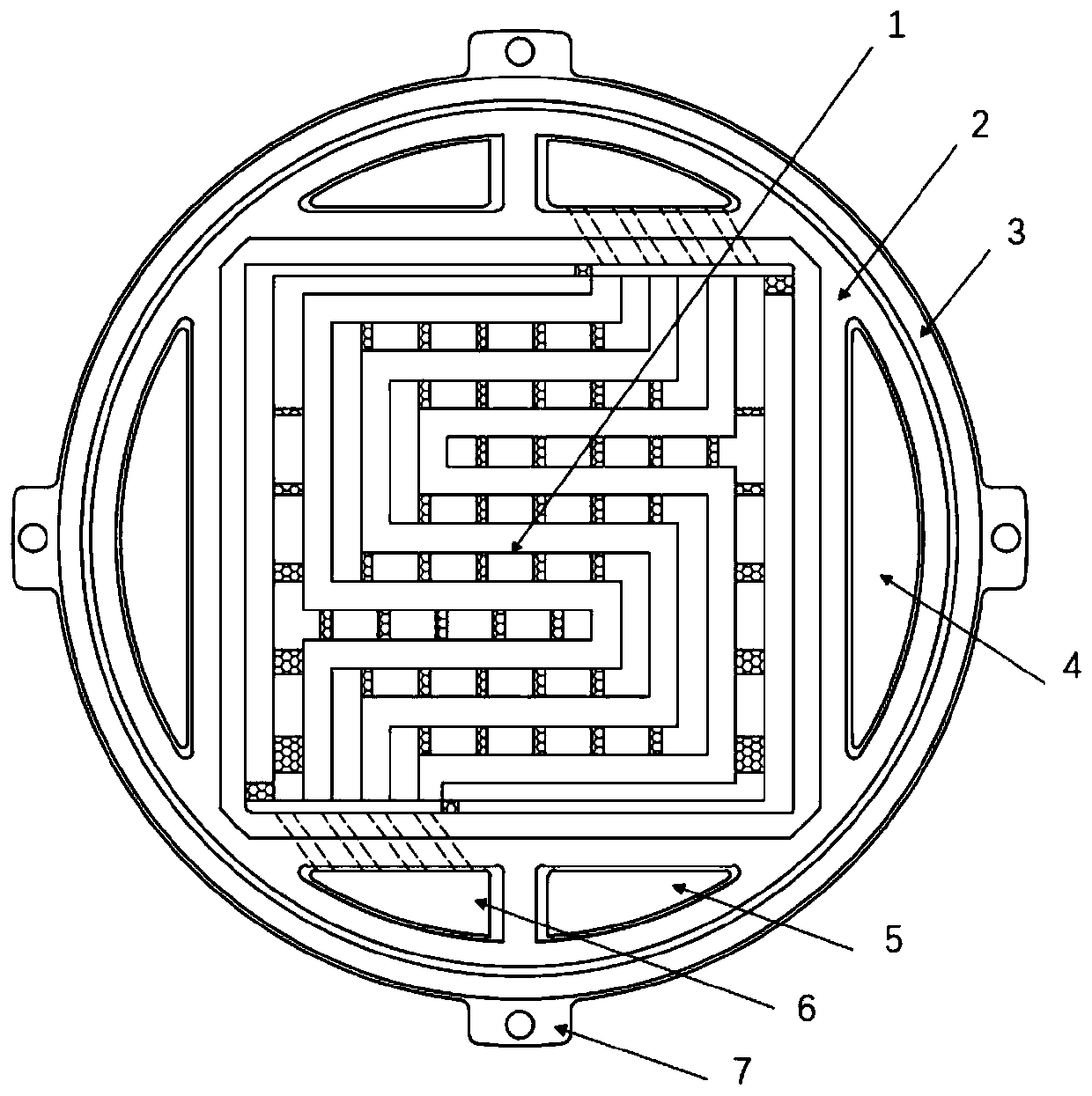
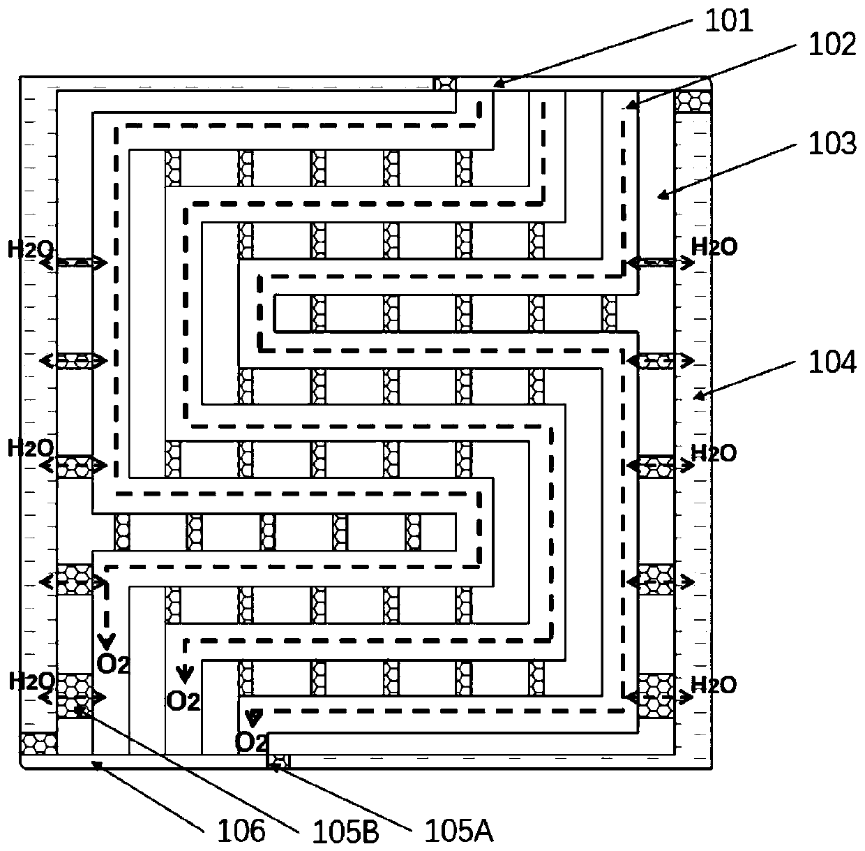
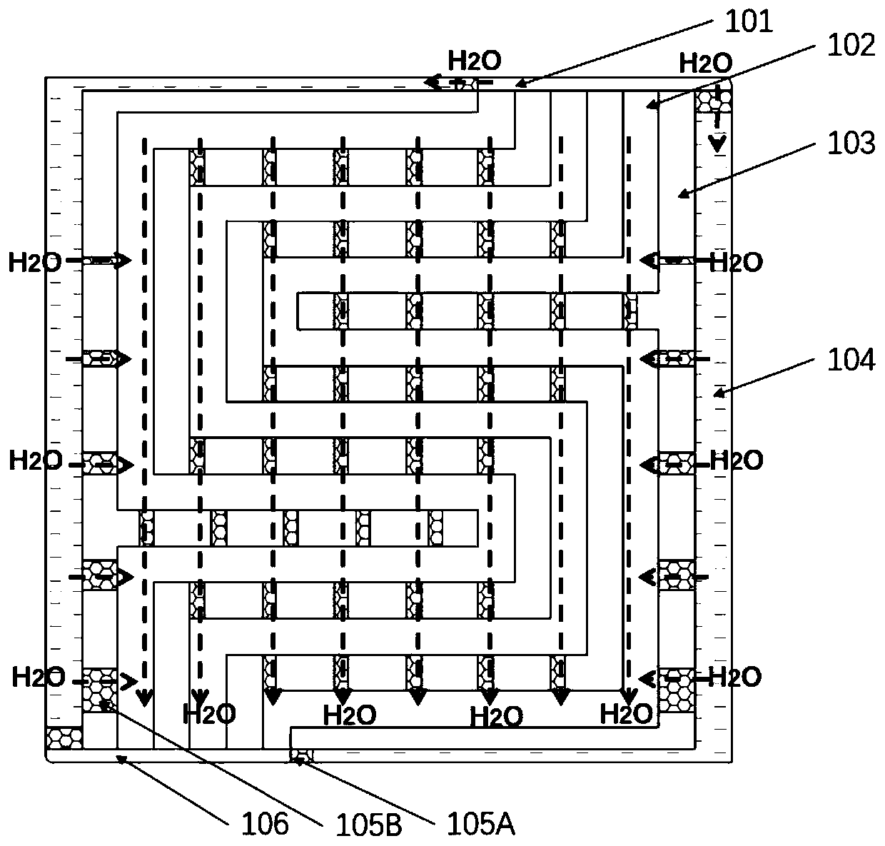
[0051] like Figure 1-5 As shown in the figure, an integrated regenerative fuel cell plate structure with adaptive flow field includes: a dual-function flow field 1, an inner sealing groove 2, an outer sealing groove 3, a coolant cavity port 4, a hydrogen cavity port 5, an oxygen cavity Port 6, positioning ear 7; dual-function flow field 1 includes: flow field inlet 101, meandering flow channel 102, flow field ridge 103, water distribution area 104, water-conducting and air-isolating structure 105, flow field outlet 106; meandering flow The channel 102 adopts a 3-channel serpentine flow channel.

[0052] The electrode plate structure of this embodiment is used as the oxygen electrode plate 8 of the integrated regenerative fuel cell, and is stacked and assembled with the bifunctional membrane electrode 9 and the hydrogen electrode plate 8' to form a single cell, which can work in two working modes of power generation and electrolysis.

[0053] In the power generation mode: the...

Embodiment 2

[0063] like Figure 3b , this embodiment is basically the same as Embodiment 1, the difference is that the water-conducting and air-insulating structure 105 is realized in another way: by machining grooves on the flow field ridge 103, and filling the water-conducting and air-insulating structures in the grooves material; this implementation reduces processing difficulties and enhances water retention. The width of the groove increases with the demand of water flux in different regions. The width is generally between 0.1mm and 1mm, and the depth of the groove is generally between 0.1mm and 0.5mm. The water-conducting and gas-barrier film can be prepared from Nafion ionomer.

Embodiment 3

[0065] This embodiment is basically the same as Embodiment 1, except that the meandering flow channel adopts a single-channel serpentine flow channel; thereby reducing the number of flow channels in the dual-function flow field and increasing the length of the flow channel; The gas barrier structure 105 and the water distribution area 104 play a more critical role; such an arrangement is more suitable for a small-area one-piece regenerative fuel cell plate.


PUM

PropertyMeasurementUnit
depthaaaaaaaaaa
depthaaaaaaaaaa

Abstract

The invention relates to a flow field self-adaptive battery plate structure and a fuel cell. The flow field self-adaptive battery plate structure is used for an integrated regenerative fuel cell, a flow field on a polar plate is a bifunctional flow field (1) which comprises a flow field inlet (101), zigzag flow channels (102) and a flow field outlet (106) which are sequentially communicated, a flow field ridge (103) is arranged between every two adjacent zigzag flow channels (102), a water guide and air isolation structure (105) is arranged on each flow field ridge (103), and a water distribution area (104) is arranged at the edge of the flow field. Compared with the prior art, the invention creatively provides the bifunctional flow field to realize the self-conversion of flow field formsin different modes of integrated regenerative fuel cell power generation and electrolysis, and in the power generation mode, the bifunctional flow field forms tend to a snake-shaped flow field with along flow channel, which is beneficial to the increase of flow field pressure drop and drainage, so that the power generation performance is improved; in the electrolysis mode, the form of the bifunctional flow field tends to the parallel flow field of a short flow channel, the uniform distribution of water is facilitated, gas generated by electrolyzing water is prevented from blocking the flow channel, and the electrolysis performance is improved.

Description

technical field [0001] The invention belongs to the technical field of fuel cells, relates to a bipolar plate assembly for a renewable fuel cell, and in particular relates to a flow field structure and a sealing structure of a renewable fuel cell suitable for power generation and electrolysis functions. Background technique [0002] An integrated regenerative fuel cell (URFC) is an electrochemical device that realizes both functions of fuel cell (power generation) and water electrolysis (charging) on ​​the same cell. With its extremely high specific energy (actual specific energy can reach 400-1000Wh / kg), high charge-discharge efficiency, cleanliness and no pollution and other characteristics, URFC is very suitable for low-weight, long-duration electricity demand, especially in space, accessibility The field of mobile power is expected to replace traditional secondary batteries, and has been listed as an important development direction of space energy technology in the futur...

Claims


Application Information

Patent Timeline
Patent Type & Authority Applications(China)
IPC IPC(8): H01M8/0258H01M8/0263H01M8/0276
CPCH01M8/0258H01M8/0263H01M8/0276H01M8/0278Y02E60/50
Inventor 彭林法李平安邱殿凯易培云来新民龚正伟靳少辉姜天豪
Owner SHANGHAI JIAO TONG UNIV
Why Eureka
Try Eureka