
Pipe cutting device for water conservancy project

A water conservancy project and cutting device technology, applied in the direction of pipe shearing device, shearing device, positioning device, etc., can solve the problems of increasing project construction cost, reducing pipe material utilization rate, unfavorable operation efficiency, etc., to improve the quality of clamping , to ensure the cutting quality, the effect of simple structure

Inactive Publication Date: 2020-08-11
高彩真
View PDF0 Cites 2 Cited by
  • Summary
  • Abstract
  • Description
  • Claims
  • Application Information

AI Technical Summary

Problems solved by technology

[0003] Water pipes are widely used in water conservancy projects. Since the pipelines in each project must be designed according to the actual working conditions, the cutting of engineering pipes is the most frequent work when laying pipelines; the existing pipe material cutting equipment does not It is convenient to cut the pipe material according to the actual use requirements, which reduces the utilization rate of the pipe material after cutting, increases the cost of engineering construction and is not conducive to the improvement of operation efficiency; therefore, it is necessary to improve the existing technology

Method used


Image

  • Pipe cutting device for water conservancy project
  • Pipe cutting device for water conservancy project
  • Pipe cutting device for water conservancy project

Examples


Embodiment 1

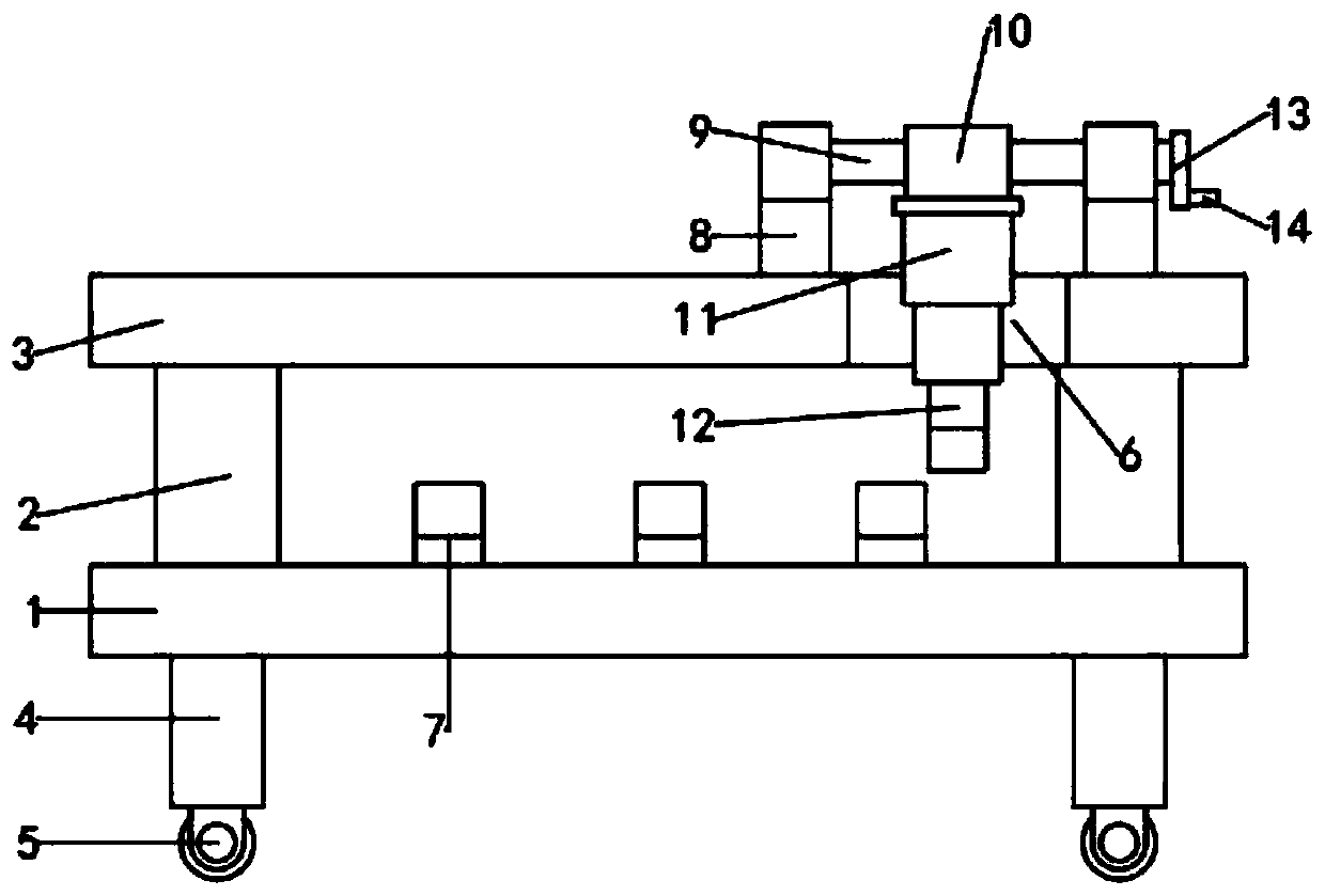
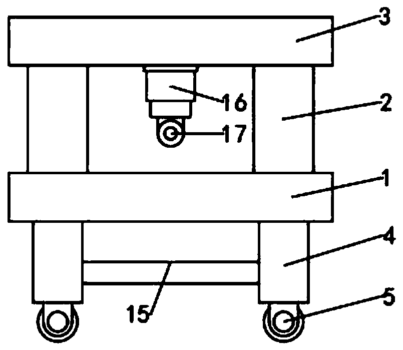
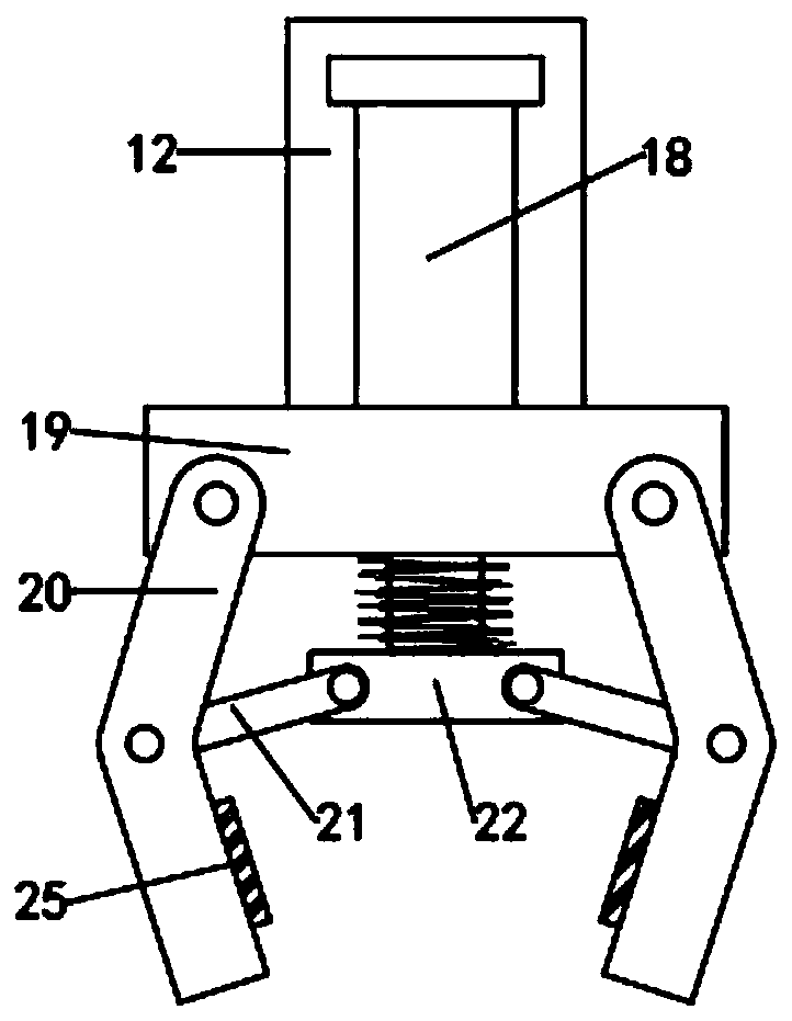
[0023] see Figure 1-6 , a pipe material cutting device for water conservancy projects, including a workbench 1, the lower end surface of the workbench 1 is fixedly connected with vertical support legs 4, the number of support legs 4 is four and arranged at four corners of a rectangle, The upper end surface of the workbench 1 is fixedly connected with a vertical support frame 2. The number of support frames 2 is four and arranged at four corners of a rectangle. The ends of the four support frames 2 facing away from the workbench 1 are connected to the mounting base 3 ; The workbench 1 is equidistantly equipped with a plurality of limit seats 7, the number of limit seats 7 is not less than three, the limit seats 7 are used to fix the pipe material to be cut, and the installation seat 3 is provided with an inlet The feeding mechanism includes an assembly seat 8, the assembly seat 8 is fixedly connected to the upper end surface of the installation seat 3, the number of the assemb...

Embodiment 2

[0032] In Embodiment 1, before the pipe material is cut, the stop block 24 and the clamping rod 20 have a fixed action on the pipe material. In order to ensure that the pipe material is not damaged during the fixing process, this embodiment uses Based on the improvement, the improvements are: the contact surfaces of the limit block 24 and the clamping rod 20 and the pipe material are uniformly provided with a protective layer 25 to prevent the surface of the pipe material from being damaged.


PUM


Abstract

The invention discloses a pipe cutting device for a water conservancy project. The pipe cutting device comprises a workbench. Multiple limiting seats are distributed on the workbench at equal distance. A feeding mechanism is distributed above the workbench and comprises assembly seats. A sliding lead screw is assembled between the two assembly seats, a sliding seat in transmission fit with the sliding lead screw is assembled on the sliding lead screw, and a vertical lifting table is fixedly connected to the lower end of the sliding seat. According to the pipe cutting device for the water conservancy project, a rocking handle can feed pipes by a proper length by controlling the clamping action of clamping rods; the work segments of limiting blocks and limiting grooves are arranged concentrically, the limiting blocks and limiting air cylinders are mounted and connected through cooperation threads, and therefore the limiting blocks of different specifications can be selected to assemble pipes of different sizes conveniently; and in addition, protection layers are distributed on the contact faces of the limiting blocks and the clamping rods with pipes, pipes can be protected conveniently, and the cutting quality of pipes is ensured.

Description

technical field [0001] The invention relates to the field of water conservancy engineering, in particular to a pipe material cutting device for water conservancy engineering. Background technique [0002] Water conservancy projects are projects built to control and allocate natural surface water and groundwater to achieve the purpose of eliminating harm and rejuvenating profits, also known as water projects. Water is an indispensable precious resource for human production and life, but its natural state does not fully meet human needs. Only by building water conservancy projects can we control water flow, prevent floods, and regulate and distribute water to meet the needs of people's life and production for water resources. Water conservancy projects need to build different types of hydraulic structures such as dams, dikes, spillways, sluices, water inlets, channels, canals, rafts, and fishways to achieve their goals. [0003] Water pipes are widely used in water conservan...

Claims


Application Information

Patent Timeline
Patent Type & Authority Applications(China)
IPC IPC(8): B23D21/00B23Q3/08B23Q7/04B25J15/02
CPCB23D21/00B23Q3/064B23Q3/08B23Q7/04B23Q7/043B23Q2703/04B25J15/0206
Inventor 高彩真
Owner 高彩真
Learn More