
Foldable enclosure device for ship air layer resistance reduction system and air layer resistance reduction ship

A technology of enclosure device and air layer, which is applied in the direction of ship hull, hull design, ship construction, etc., can solve the problem of large ship bottom reconstruction and achieve the effect of increasing stability

Pending Publication Date: 2020-08-11
CSIC SHANGHAI MARINE ENERGY SAVING TECH DEV CO LTD
View PDF0 Cites 4 Cited by
  • Summary
  • Abstract
  • Description
  • Claims
  • Application Information

AI Technical Summary

Problems solved by technology

[0004] The purpose of the present invention is to provide a foldable enclosure device and an air layer drag reduction ship for a ship's air layer drag reduction system, so as to solve the problem of the installation of the enclosure device in the air layer drag reduction system in the prior art. big problem

Method used


Image

  • Foldable enclosure device for ship air layer resistance reduction system and air layer resistance reduction ship
  • Foldable enclosure device for ship air layer resistance reduction system and air layer resistance reduction ship
  • Foldable enclosure device for ship air layer resistance reduction system and air layer resistance reduction ship

Examples


Embodiment 1

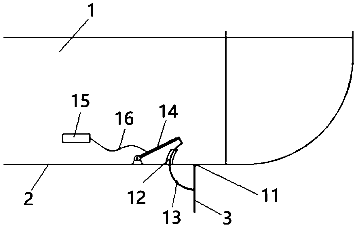
[0053] see Figure 1 to Figure 8 , the present embodiment provides a foldable enclosure device for the air layer drag reduction system of the ship, which is installed on the flat bottom 2 of the air layer drag reduction ship, and the top of the flat bottom 2 is the bilge. A foldable shroud device used for a ship air layer drag reduction system includes a plurality of cavitation shrouds and a plurality of driving structures. Each air pocket coaming is rotatably connected to the lower surface of the flat bottom 2 of the ship. After each air pocket coaming is rotated and unfolded, it cooperates to form an air cavity for accommodating the air layer of the air layer drag reduction ship. Each cavitation coaming is equipped with one or more driving structures respectively. The driving structure includes a driving part and a transmission part. The driving part is arranged in the bilge tank. The coaming is connected, and a sealing structure is provided between the transmission part an...

Embodiment 2

[0074] Please see figure 2 , Figure 5 to Figure 8 , On the basis of Embodiment 1, this embodiment is provided with a bow wedge block 9 and a stern wedge block 10 .

[0075] Both the bow coaming 4 and the transom 5 have a first side connected to the flat 2 and a second side corresponding to the first side.

[0076]The bow flexible part 7 is arranged on the stern side of the bow coaming, and the bow flexible part 7 is respectively connected with the flat bottom 2 and the second side of the bow coaming 4. In the unfolded state, the bow flexible part 7, the bow The coaming 4 and the ship's flat bottom 2 cooperate to form a first triangular structure, and the first triangular area is the bow wedge 8; The distance between the flat bottom 2.

[0077] The stern side of the stern coaming is provided with a stern flexible part 8 which is respectively connected to the second side of the flat bottom 2 and the stern coaming 5. In the unfolded state, the stern flexible part 8, the ster...

Embodiment 3

[0083] Please see figure 1 , image 3 and Figure 4 , On the basis of Embodiment 1 or Embodiment 2, a plurality of air cavity partitions 6 are arranged in the air cavity, that is, the air cavity coamings are all located between two ship side coamings 3 .

[0084] Each cavitation partition 6 is connected to the lower surface of the ship's flat bottom 2 in rotation along the ship's length direction, and divides the cavitation into a plurality of air cavities. Preferably, the plurality of air pocket separators 6 are symmetrical with respect to the center line of the bottom of the ship, and divide the air pocket into multiple air cavities on average.

[0085] Each cavitation barrier 6 is equipped with one or more drive structures as described in Embodiment 1, respectively. The connection and the positional relation of concrete cavitation partition 6 and driving structure, ship's flat bottom 2 are identical with the connection and positional relation of ship side coaming 3 and d...


PUM


Abstract

The invention discloses a foldable fence device for a ship air layer drag reduction system, which is arranged on a ship flat bottom of an air layer drag reduction ship, a ship bottom cabin is arrangedabove the ship flat bottom, and the foldable fence device comprises a plurality of air hole coamings and a plurality of driving structures. The cavitation coamings are rotationally connected to the lower surface of the flat bottom of the ship, and after the cavitation coamings are rotationally unfolded, the cavitation coamings are matched to define a cavitation used for containing an air layer ofthe air layer drag reduction ship. Each cavitation coaming is provided with one or more driving structures, each driving structure comprises a driving part and a transmission part, the driving partsare arranged in the ship bottom cabin, one end of each transmission part is connected with the corresponding driving part, the other end of each transmission part penetrates through the ship bottom tobe connected with the corresponding cavitation coaming, and a sealing structure is arranged between each transmission part and the ship bottom; the driving piece drives the cavitation coaming to rotate relative to the boat flat bottom through the transmission piece, and unfolding or folding of the cavitation coaming is achieved. According to the ship bottom cutting device, the ship bottom needs to be cut and machined only at the position where the transmission part penetrates through, and therefore transformation of the ship bottom is small.

Description

technical field [0001] The invention belongs to the technical field of an air layer drag reduction system at the bottom of a ship, and in particular relates to a foldable enclosure device for an air layer drag reduction system of a ship and an air layer drag reduction ship. Background technique [0002] Ship air layer drag reduction is a technology to reduce the frictional resistance of the sailing hull by injecting air to the bottom of the ship to form an air layer covering the bottom of the ship to reduce the wet surface area of ​​the hull. The air injection system currently used is in the form of bottom grooves and longitudinal coamings. The form of longitudinal coaming has a higher degree of acceptance due to small changes to the hull, but it has an impact on the draft of the ship (during shallow water channel navigation), and in the non-jet state, the additional resistance of the hull increases after the longitudinal coaming is installed on the bottom of the ship. [00...

Claims


Application Information

Patent Timeline
Patent Type & Authority Applications(China)
IPC IPC(8): B63B1/38
CPCB63B1/38B63B2001/387Y02T70/10
Inventor 陈雷强吴赞高丽瑾朱玉柱陈少峰恽秋琴
Owner CSIC SHANGHAI MARINE ENERGY SAVING TECH DEV CO LTD
Learn More