Hydraulic hybrid power excavator hydraulic system with switching control function

A hydraulic system and hybrid technology, applied in the hydraulic system field of hydraulic hybrid excavators, can solve the problems of large transformation and high manufacturing cost, achieve the effect of reducing the difficulty and cost of transformation, and continuing the advantages of energy saving

Active Publication Date: 2013-10-23
HARBIN INST OF TECH +1
View PDF5 Cites 12 Cited by
  • Summary
  • Abstract
  • Description
  • Claims
  • Application Information

AI Technical Summary

Problems solved by technology

However, with this configuration, the quantitative motors in the existing excavator manufacturing system must be replaced with hydraulic pumps/motors that can

Method used


Image

  • Hydraulic hybrid power excavator hydraulic system with switching control function

Examples


specific Embodiment approach 1

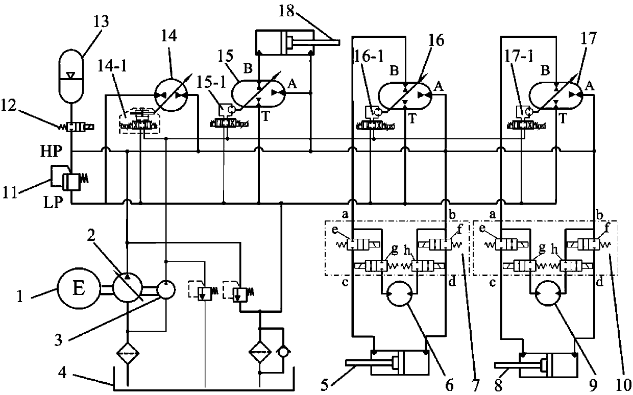
[0013] Specific implementation mode one: as figure 1 As shown, the switching control hydraulic hybrid excavator hydraulic system described in this embodiment includes an engine 1, a constant pressure variable pump 2, a control oil circuit pump 3, a fuel tank 4, a bucket hydraulic cylinder 5, a first travel Quantitative motor 6, first switching valve group 7, stick hydraulic cylinder 8, second walking quantitative motor 9, second switching valve group 10, overflow valve 11, electric control switching valve 12, hydraulic accumulator 13, rotation variable Pump / motor 14, first hydraulic transformer 15, second hydraulic transformer 16, third hydraulic transformer 17 and boom hydraulic cylinder 18; engine 1 is coaxially mechanically connected with control oil circuit pump 3 through constant pressure variable pump 2 ;

[0014] The oil inlet port of the constant pressure variable pump 2 is connected to the oil tank 4, and the oil outlet port of the constant pressure variable pump 2 i...

specific Embodiment approach 2

[0017] Specific implementation mode two: as figure 1 As shown, in this embodiment, both the first switching valve group 7 and the second switching valve group 10 are composed of four electronically controlled switching valves; An electronically controlled on-off valve is respectively arranged at both ends, and an electronically controlled on-off valve is respectively arranged on the branch oil road with the first traveling quantitative motor 6 and located at both ends of the first traveling quantitative motor 6; An electronically controlled on-off valve is provided on the oil circuit at both ends of the stick hydraulic cylinder 8, and an electronically controlled on-off valve is provided on the branch oil circuit with the second travel quantitative motor 9 and located at both ends of the second travel quantitative motor 9 . Other components and connections are the same as those in the first embodiment.

specific Embodiment approach 3

[0018] Specific implementation mode three: as figure 1 As shown, the rotary variable pump / motor 14 in this embodiment has a rotary variable pump / motor control assembly 14-1. Other compositions and connections are the same as those in Embodiment 1 or 2.


PUM


Abstract

The invention discloses a hydraulic hybrid power excavator hydraulic system with a switching control function, and relates to an excavator hydraulic system, aiming at realizing the excavator hydraulic system and reducing the manufacturing cost. An A port of a second hydraulic transformer is communicated with a rodless cavity oil port of a bucket hydraulic cylinder; a rod cavity oil port of the bucket hydraulic cylinder is communicated with a B port of the second hydraulic transformer; the two oil ports of the bucket hydraulic cylinder are connected in parallel with a first travel constant displacement motor; a loop formed between the bucket hydraulic cylinder and the first travel constant displacement motor is provided with a first switching valve bank; an A port of a third hydraulic transformer is communicated with the rodless cavity oil port of the bucket hydraulic cylinder; the rod cavity oil port of the bucket hydraulic cylinder is communicated with a B port of the third hydraulic transformer; the two oil ports of the bucket hydraulic cylinder are connected in parallel with a second travel constant displacement motor; and a loop formed between the bucket hydraulic cylinder and the second travel constant displacement motor is provided with a second switching valve bank. The switching control over the travel constant displacement motors is realized by using the hydraulic transformers for controlling the bucket and a bucket rod through two valve banks, so that the reconstruction difficulty and cost are reduced.

Description

technical field [0001] The invention relates to a hydraulic system of an excavator, in particular to a hydraulic system of a hydraulic hybrid excavator with a switching function. Background technique [0002] In recent years, with the aggravation of the energy crisis and the increasingly stringent emission requirements, the research on energy saving and emission reduction of excavators is becoming a hot topic for the majority of scientific researchers and various host manufacturers. In recent years, the research on energy saving of excavators has achieved some fruitful results, such as positive flow technology, negative flow technology and load sensing technology, etc. The proposals of these solutions have played a positive role in reducing fuel consumption, but these solutions cannot be recycled Energy, so the space for energy saving is limited. For hybrid excavators using electric hybrid technology, although energy can be recovered, the energy conversion has gone through ...

Claims


Application Information

Patent Timeline
IPC IPC(8): E02F9/22F15B1/02F15B15/08
Inventor 姜继海沈伟汪泽波
Owner HARBIN INST OF TECH
Why Eureka
Try Eureka