
MEMS bridge column structure and manufacturing method thereof

A manufacturing method and technology of bridge columns, applied in the direction of microstructure technology, microstructure devices, manufacturing microstructure devices, etc., can solve problems such as bridge column collapse and bridge structure warping

Pending Publication Date: 2020-08-11
SHANGHAI HUAHONG GRACE SEMICON MFG CORP
View PDF7 Cites 0 Cited by
  • Summary
  • Abstract
  • Description
  • Claims
  • Application Information

AI Technical Summary

Problems solved by technology

There is a risk of buckling of the bridge structure and collapse of bridge columns due to stresses within the amorphous silicon layer and electrode layers

Method used


Image

  • MEMS bridge column structure and manufacturing method thereof
  • MEMS bridge column structure and manufacturing method thereof
  • MEMS bridge column structure and manufacturing method thereof

Examples


Embodiment 1

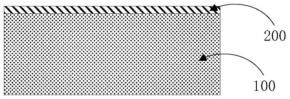
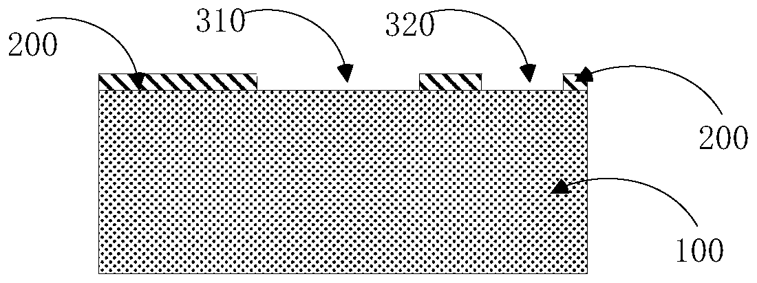
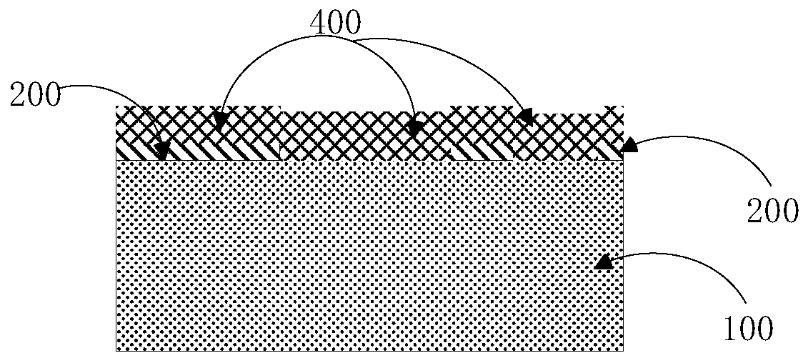
[0044] Figure 1A to Figure 1E Explained the schematic diagram of the structure after the completion of each step in the manufacturing method of the MEMS bridge column structure of the application, the manufacturing method of the MEMS bridge column structure of the application includes:

[0045] Step 1: providing a substrate 100; the material of the substrate 100 can be at least one of silicon, silicon dioxide or amorphous silicon.

[0046] Step 2: Refer to Figure 1A , depositing a titanium-containing thin film layer 200 on the upper surface of the substrate 100; wherein, the material of the titanium-containing thin film layer 200 can be at least one of titanium or titanium nitride, and when the material of the titanium-containing thin film layer 200 only adopts a single titanium, then the titanium-containing thin film layer 200 is a titanium thin film layer, and when the material of the titanium-containing thin film layer 200 adopts a single titanium nitride, the titanium-co...

Embodiment 2

[0058] In this embodiment, on the basis of Embodiment 1, the stress of the titanium-containing thin film layer 200 is: -0.1 GPa˜3 GPa; the stress of the amorphous silicon layer 400 is: 0 MPa˜30 MPa.

Embodiment 3

[0060] In this embodiment, on the basis of Embodiment 1, the second step includes: depositing and forming a titanium-containing thin film layer 200 on the upper surface of the substrate 100 by PVD process. Optionally, the deposited titanium-containing thin film layer 200 has a thickness of 100-200 Å.


PUM

PropertyMeasurementUnit
Stressaaaaaaaaaa
Stressaaaaaaaaaa

Abstract

The invention relates to the technical field of semiconductor integrated circuits, in particular to an MEMS bridge column structure and a manufacturing method thereof. The method comprises the following steps: providing a substrate; depositing a titanium-containing film layer on the substrate; etching the titanium-containing thin film layer to form an isolation groove and a connection groove, theisolation groove and the connection groove extending downwards from the upper surface of the titanium-containing thin film layer to the etching stop surface of the substrate; depositing an amorphous silicon layer on the non-etched titanium-containing thin film layer and in the isolation groove and the connection groove; etching the amorphous silicon layer, and removing the amorphous silicon layerin the isolation groove; and depositing a silicon dioxide layer on the amorphous silicon layer and in the isolation groove. The structure comprises a substrate; the titanium-containing thin film layeris deposited on the substrate, and an isolation groove and a connecting groove are formed in the titanium-containing thin film layer; the isolation groove and the connecting groove extend downwards from the upper surface of the titanium-containing thin film layer to the etching stop surface of the substrate; the amorphous silicon layer is deposited on the residual titanium-containing thin film layer and is filled in the connecting groove; and the silicon dioxide layer is deposited on the amorphous silicon layer and is filled in the isolation groove.

Description

technical field [0001] The present application relates to the technical field of semiconductor integrated circuits, in particular to a MEMS bridge column structure and a manufacturing method thereof. Background technique [0002] Micro-Electro-Mechanical System (MEMS) technology has many advantages such as smallness, intelligence, execution, integration, and good process compatibility, and is suitable for wide application in many fields. The MEMS bridge structure is a widely used structure in the MEMS bridge column structure. In the MEMS bridge structure, the MEMS bridge column plays a very critical role in the electrical connection of the bridge structure. [0003] In related technologies, the MEMS bridge column adopts a composite film layer structure, including: a substrate, an amorphous silicon layer, an electrode layer and an oxide layer stacked in sequence. Due to stresses within the amorphous silicon layer and the electrode layer, there is a risk of warping the bridge...

Claims


Application Information

Patent Timeline
IPC IPC(8): B81C1/00B81B7/00B81B7/02
CPCB81C1/00301B81B7/007B81B7/02
Inventor 刘善善朱黎敏
Owner SHANGHAI HUAHONG GRACE SEMICON MFG CORP
Learn More