
Flange connection device for improving composite pipe structure stability

A technology of structural stability and connection device, which is applied in flange connection, pipeline connection arrangement, pipe/pipe joint/pipe fittings, etc., can solve the problems of easy crushing on the surface of the pipe and the effect of the pipe sealing effect, and achieves the protection of , the structure is simple, the effect of improving the utilization rate

Inactive Publication Date: 2020-08-11
泉州市泉港区涂岭镇盛芳工业设计服务中心
View PDF0 Cites 2 Cited by
  • Summary
  • Abstract
  • Description
  • Claims
  • Application Information

AI Technical Summary

Problems solved by technology

[0003] The invention provides a flange-type connection device for composite pipes to overcome the problems existing in the existing composite pipe connection structure that the surface of the pipe is easily crushed during transportation or storage, and the sealing effect between the pipes is affected.

Method used


Image

  • Flange connection device for improving composite pipe structure stability
  • Flange connection device for improving composite pipe structure stability
  • Flange connection device for improving composite pipe structure stability

Examples


Embodiment approach 1

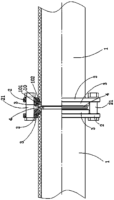
[0016] refer to figure 1 , a flange connection device that improves the structural stability of the composite pipe, and the connection device is used for the fixed connection of the ends of two composite pipes 1 . The connecting device comprises two flanges 2 , four connecting pieces 3 and one sealing piece 4 . The connecting piece 3 is preferably semi-circular, and the cross section of the connecting piece 3 is in the shape of a "7" or a shape of a "T". The end of each composite pipe 1 is preferably provided with two connecting pieces 3, and the two connecting pieces 3 are spliced ​​to form a ring structure. The seal 4 is assembled on the connecting end faces of the two composite pipes 1, and the seal 4 adopts a rubber O-ring or an annular gasket. The connecting end of the composite pipe 1 is provided with an installation groove 10, the groove wall adjacent to the seal 4 of the installation groove 10 is the near groove wall 101, the groove wall away from the seal 4 is the f...

Embodiment approach 2

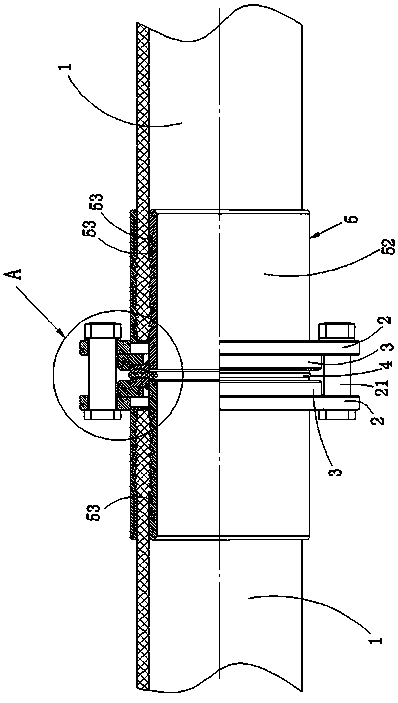
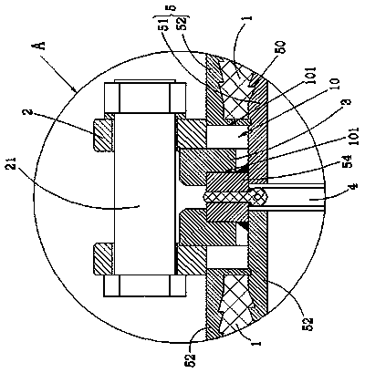
[0019] refer to figure 2 , image 3 The difference between this embodiment and Embodiment 1 is that in this embodiment, a connecting pipe 5 is fixedly arranged at each end of the composite pipe 1, and the connecting pipe 5 is preferably made of a material with high structural strength and is not easily corroded. become. refer to figure 2 , the connecting pipe 5 is integrally formed by connecting an inner pipe 51 and an outer pipe 52, the inner end of the inner pipe 51 is inserted into the composite pipe 1, the outer pipe 52 is sleeved on the outer wall of the composite pipe 1, and the inner pipe 51 The outer surface of the end is provided with a tooth groove 50, and the inner wall of the outer tube 52 is also provided with a tooth groove 50. Two rubber sealing rings 53 are arranged on the connecting surface of the composite pipe 1 and the outer pipe 52, and the external force is applied to make the composite pipe The plastic parts of the inner and outer surfaces of 1 sink...


PUM


Abstract

The invention relates to a flange connection device for improving composite pipe structure stability. The device comprises at least two flanges and a sealing element, and the sealing element is assembled on a connection end face of two composite pipes; the composite pipe connection end is provided with a mounting groove, a groove wall, adjoined to the sealing element, of the mounting groove is a near groove wall, the groove wall, departed from the sealing element, is a remote groove wall, and height of the near groove wall is less than or equal to height of the remote groove wall; the mountinggroove is configured with a connection piece, the connection piece is buckled on a top edge of the near groove wall, a side wall of the flange connects the connection piece through supporting and pressing, and the two composite pipes are in locked connection through the flange. With the connection device provided by the invention, arrangement of a protruding structure is not needed for an end part of the composite pipe, moreover, the flange, the connection piece and the composite pipe are all in a separate state, thus, protection for a pipe wall of a pipeline during transportation or storageis facilitated, damage rate of the pipe wall and deformation rate of the end part of the pipeline are reduced effectively, consequently, connection precision of the end part of the pipeline is guaranteed, and airtightness is guaranteed.

Description

technical field [0001] The invention relates to a connecting device for pipelines, in particular to a flanged connecting device for composite pipes. Background technique [0002] In the prior art, several sections of composite pipes are connected into a complete pipeline through flange fixed connection. The flange connection method requires the end of the composite pipe to be fixed with a force component (that is, the connecting ring in this technology). When the flange is locked, the force component at the end of the two composite pipes is clamped to achieve the effect of pipe connection. Since the construction site rarely has complete auxiliary welding equipment, most of the existing composite pipes will be fixedly welded with force components at the ends before leaving the factory. If the force component is to be sandwiched between the flanges, then the outer diameter of the force component must be larger than the outer diameter of the composite pipe, that is, both ends ...

Claims


Application Information

Patent Timeline
Patent Type & Authority Applications(China)
IPC IPC(8): F16L47/14F16L23/028
CPCF16L23/0286F16L47/14
Inventor 王芳云陈婉珍
Owner 泉州市泉港区涂岭镇盛芳工业设计服务中心
Learn More